Lean oil direct injection and mixing low-pollution combustion chamber

A combustion chamber and low-pollution technology, applied in the direction of combustion chambers, continuous combustion chambers, combustion methods, etc., can solve problems such as increased inlet temperature and inlet pressure of the combustion chamber, combustion instability, spontaneous combustion risk, etc., to reduce risks and expand The effect of stabilizing the working range and avoiding spontaneous combustion and flashback phenomena

Active Publication Date: 2018-01-05
NORTHWESTERN POLYTECHNICAL UNIV
View PDF15 Cites 23 Cited by
  • Summary
  • Abstract
  • Description
  • Claims
  • Application Information

AI Technical Summary

Problems solved by technology

At present, domestic low-pollution combustors widely adopt the staged combustion strategy, and the main combustion stage generally adopts the premixed pre-evaporation combustion method. Under the existing engine working conditions, this is indeed a very effective method for reducing pollutants. However, with the In the future, the working state of the engine will be greatly improved, and the inlet temperature and inlet pressure of the combustion chamber will increase significantly. The use of premixed and pre-evaporation methods will bring backfire and spontaneous combustion risks, and may cause serious combustion instability problems. Therefore, for future civil aviation The working state of the engine urgently needs a low-pollution combustion chamber that can not only ensure the stable operation of the combustion chamber, but also meet the pollution emission requirements.

Method used


Image

  • Lean oil direct injection and mixing low-pollution combustion chamber
  • Lean oil direct injection and mixing low-pollution combustion chamber
  • Lean oil direct injection and mixing low-pollution combustion chamber

Examples


Embodiment Construction

[0028] Now in conjunction with embodiment, accompanying drawing, the present invention will be further described:

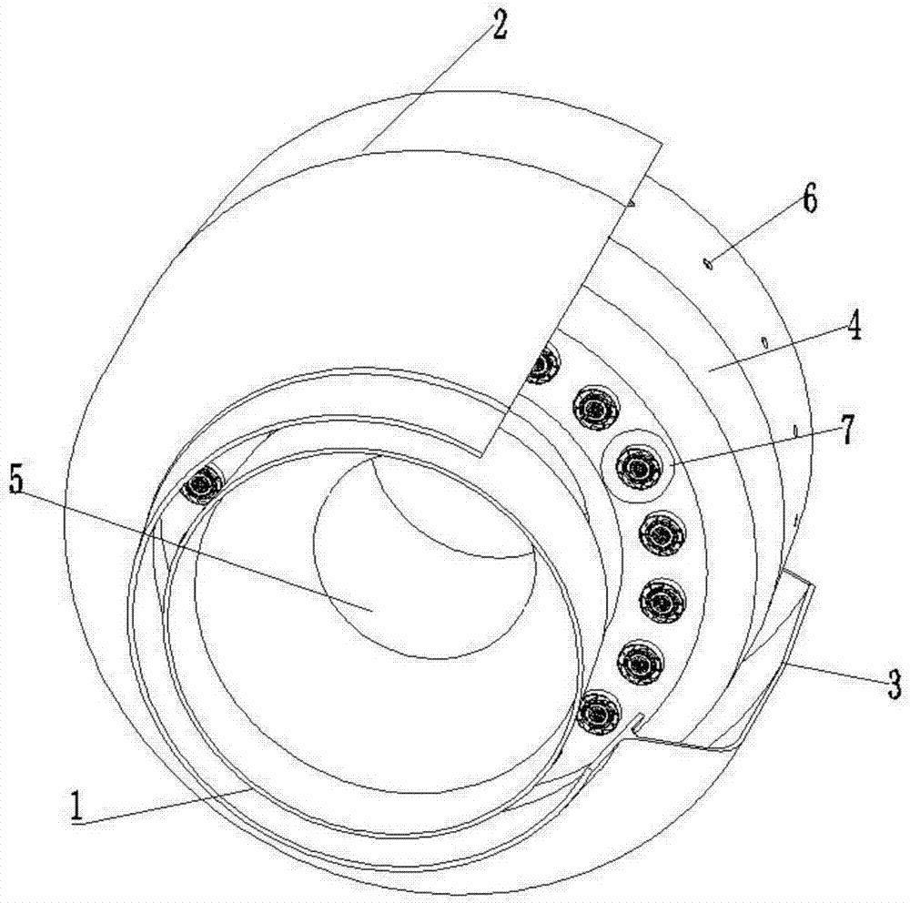
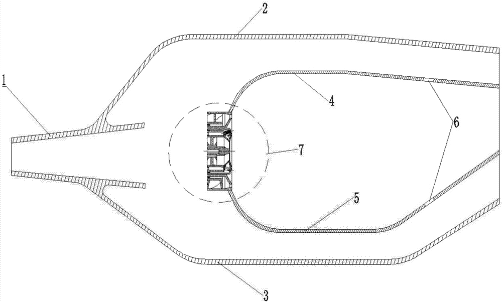
[0029] The present invention adopts the following technical solutions: a low-pollution combustion chamber based on lean oil direct injection and mixing, including a diffuser, a casing outside the combustion chamber, a casing inside the combustion chamber, the outer wall of the flame tube, the inner wall of the flame tube, the mixing hole and the combustion chamber. chamber head. The high-speed air flow is decelerated and diffused by the diffuser and then divided into three streams. One stream enters the outer ring cavity formed by the casing outside the combustion chamber and the outer wall of the flame tube, and one enters the inner ring cavity surrounded by the casing inside the combustion chamber and the inner wall of the flame tube. The strand enters the combustion zone surrounded by the outer wall of the flame tube and the inner wall of the flame tube from t...


PUM


Abstract

The invention relates to a lean oil direct injection and mixing low-pollution combustion chamber. The lean oil direct injection and mixing low-pollution combustion chamber is composed of a diffuser, acombustion chamber outer case, a combustion chamber inner case, a combustion chamber head, a flame tube outer wall and a flame tube inner wall, wherein combustion air all enters a flame tube from thecombustion chamber head; the combustion chamber head is divided into an on-duty grade and a main combustion grade through a grading and partitioning combustion strategy; the on-duty grade and the main combustion grade both adopt a direct injection and mixing combustion method, the phenomena of spontaneous combustion and tempering are effectively avoided, and the risk of occurrence of oscillationcombustion is lowered; the lean oil direct injection and mixing low-pollution combustion chamber only works in an on-duty grade mode under an idling rating state, the designed partial equivalence ratio is higher, and the work stability of the combustion chamber is guaranteed; and with the increase of the work state of the combustion chamber, the main combustion grade is opened gradually, the maincombustion grade and the on-duty grade work simultaneously under a large state, the designed combustion area average equivalence ratio is lower, the average temperature of the combustion area is effectively lowered, and therefore the generation quantity of pollutants is lowered.

Description

technical field [0001] The invention belongs to the field of low-pollution combustion chambers, and relates to a lean oil direct injection and mixed low-pollution combustion chamber. Background technique [0002] In recent years, the international community has paid more and more attention to environmental protection issues. Although the pollutant emissions of aero-engines account for a small proportion of the total environmental pollution emissions, high-altitude pollutants mainly come from aero-engines. Therefore, CAEP, the Environmental Protection Committee of ICAO, has formulated a series of standards to strictly regulate the emissions of CO, UHC and NOx from civil aircraft engines. Only engines that meet the emission requirements can obtain airworthiness certification. Therefore, it is necessary to vigorously develop low-pollution combustion technology to reduce the emission level of aero-engine pollutants, so as to meet the higher emission requirements now and in the f...

Claims


Application Information

Patent Timeline
Patent Type & Authority Applications(China)
IPC IPC(8): F23R3/14F23R3/38F23R3/42
Inventor 于涵孙付军李乐朱鹏飞徐丁欢
Owner NORTHWESTERN POLYTECHNICAL UNIV
Why Eureka
Try Eureka