
Throttling and flow dividing assembly and air conditioner

A component and split port technology, applied in the direction of refrigeration components, fluid circulation arrangements, refrigerators, etc., can solve problems such as the impact of split flow at installation locations, low assembly efficiency, and large quantities, so as to improve stability and reliability and improve operating efficiency , the effect of improving stability

Pending Publication Date: 2018-01-05
GD MIDEA HEATING & VENTILATING EQUIP CO LTD +1
View PDF5 Cites 4 Cited by
  • Summary
  • Abstract
  • Description
  • Claims
  • Application Information

AI Technical Summary

Problems solved by technology

[0003] The first is the system efficiency problem, that is, the liquid refrigerant will generally become a gas-liquid two-phase state after being throttled and depressurized by the throttling element. Due to the complex and changeable state of the two-phase flow, when the distribution head and the capillary tube are used to divide and adjust it It is often difficult to achieve the ideal state. Even if the evaporation state of each flow path is adjusted uniformly under a certain working condition, when the working condition changes, the pressure difference between the front and rear of the throttling element, the refrigerant circulation amount, the two-phase flow state and the state parameters fluctuate. Larger, resulting in the poor ability of the previously designed distribution head and capillary tube components to adapt to the new working conditions, the heat transfer efficiency of the evaporator and the system capacity will be affected. have an impact on diversion
[0004] The second is the process problem, especially for the evaporator of a large air conditioner, due to the uneven wind field of each flow path, the heat transfer effect is significantly different, resulting in a large difference in the length of the capillary tube, coupled with the large number, resulting in welding and bending process Complicated, and there is also the risk of incorrect correspondence between the capillary and the flow path assembled in the production line, so the assembly efficiency is low
[0005] To sum up, the throttling and diverting processes of traditional air conditioners occur in different parts, resulting in the liquid refrigerant after throttling being in a gas-liquid two-phase state, and the bias flow phenomenon is very easy to occur at the distribution head. The degree of bias flow varies with the ambient temperature and the two phases. There are big differences due to different phase flow states. At the same time, the assembly and welding process of the traditional distribution head and capillary shunt components is also relatively complicated.

Method used


Image

  • Throttling and flow dividing assembly and air conditioner
  • Throttling and flow dividing assembly and air conditioner
  • Throttling and flow dividing assembly and air conditioner

Examples


Embodiment Construction

[0041] In order to understand the above-mentioned purpose, features and advantages of the present invention more clearly, the present invention will be further described in detail below in conjunction with the accompanying drawings and specific embodiments. It should be noted that, in the case of no conflict, the embodiments of the present application and the features in the embodiments can be combined with each other.

[0042] In the following description, many specific details are set forth in order to fully understand the present invention, but the present invention can also be implemented in other ways different from those described here, therefore, the protection scope of the present invention is not limited to the specific details disclosed below. EXAMPLE LIMITATIONS.

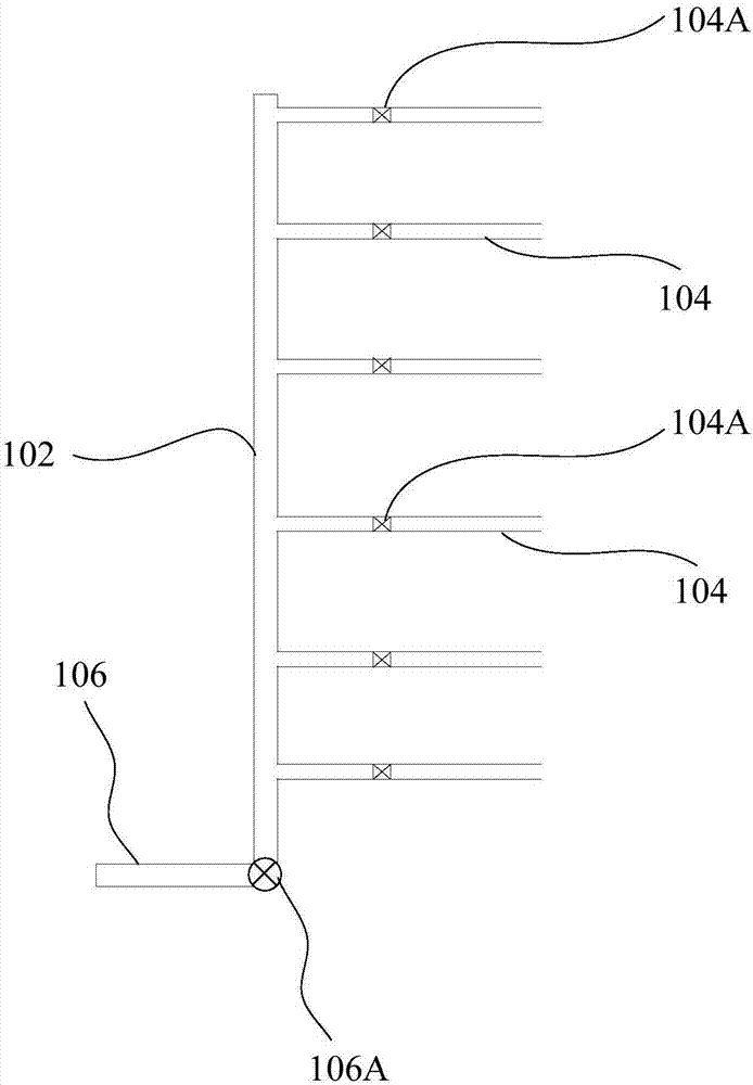
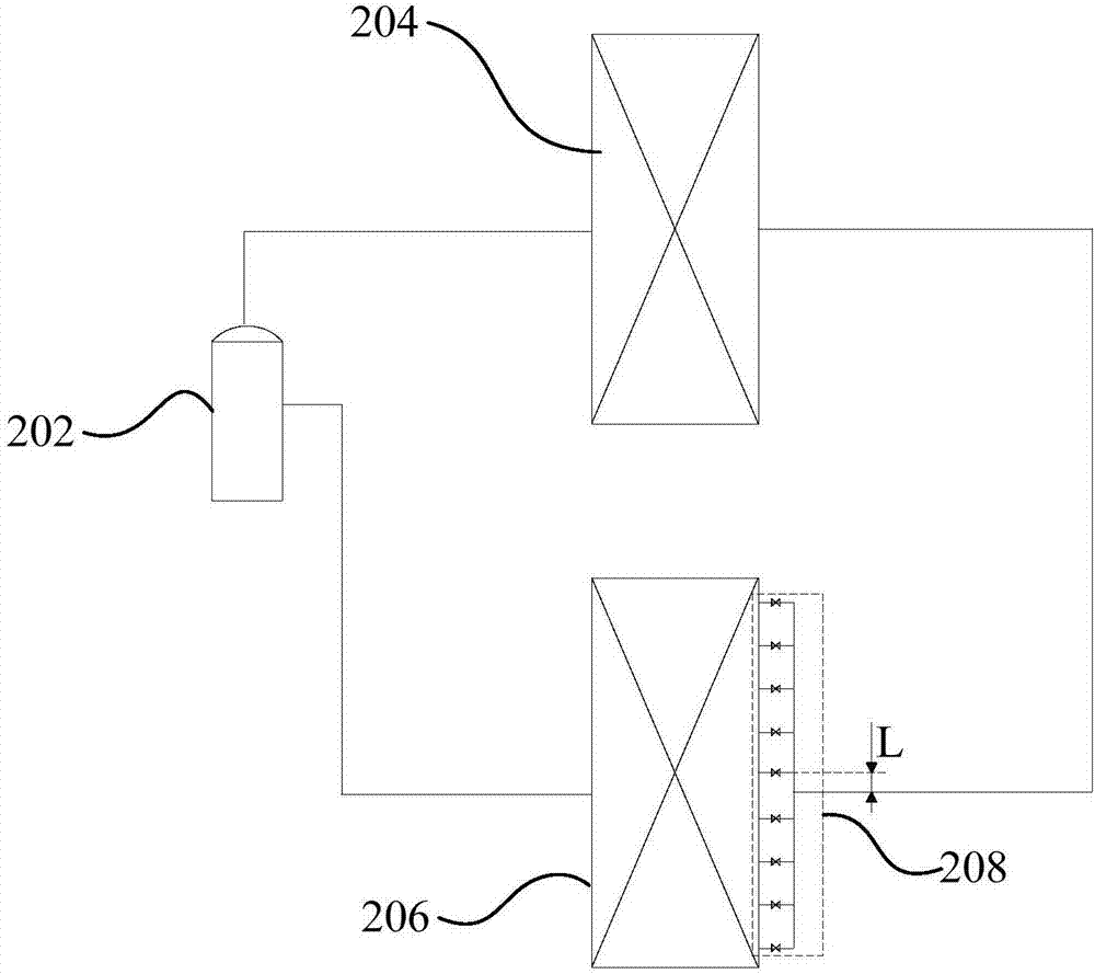
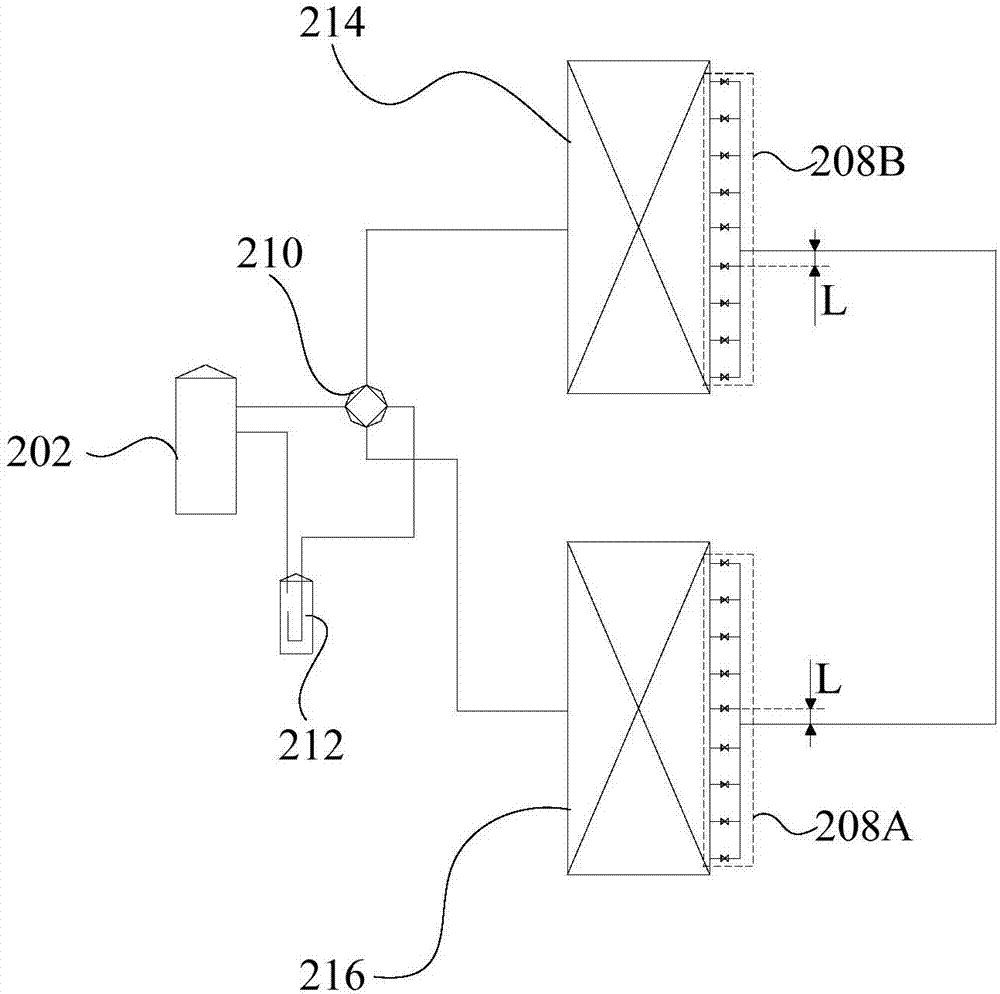
[0043] Combine below Figure 1 to Figure 3 The throttling and splitting assembly according to the embodiment of the present invention will be described in detail.

[0044] Such as figure 1 and figure...


PUM


Abstract

The invention provides a throttling and flow dividing assembly and an air conditioner. The throttling and flow dividing assembly comprises a main pipe and a plurality of branch pipes; a plurality of flow dividing openings are formed in the side wall of the main pipe; the multiple branch pipes communicate with the multiple flow dividing openings in a one-to-one correspondence mode; and a throttlingdevice is arranged in any branch pipe. Through the technical scheme, liquid in the main pipe can evenly flow towards all the branch pipes through the corresponding flow dividing openings, and thus the good flow dividing effect is achieved; and each branch pipe is provided with the corresponding throttling device, and the liquid flowing into all the branch pipes is subjected to throttling and depressurizing through the throttling devices, so that the stability of the flow dividing and throttling processes of the liquid is improved.

Description

technical field [0001] The invention relates to the field of air conditioners, in particular to a throttling and diverting assembly and an air conditioner. Background technique [0002] At present, in the existing air conditioning system, the throttling and splitting process of liquid refrigerant is carried out in two different parts and completed by different components, which usually include throttling elements, distribution heads and splitting capillaries. However, The above scheme has two obvious disadvantages: [0003] One is the system efficiency problem, that is, the liquid refrigerant will generally become a gas-liquid two-phase state after being throttled and depressurized by the throttling element. Due to the complex and changeable state of the two-phase flow, when it is adjusted by the distribution head and the capillary It is often difficult to achieve the ideal state. Even if the evaporation state of each flow path is adjusted uniformly under a certain working ...

Claims


Application Information

Patent Timeline
IPC IPC(8): F25B41/00F25B41/06F25B41/30F25B41/42
Inventor 彭泉贵靳晓钒
Owner GD MIDEA HEATING & VENTILATING EQUIP CO LTD
Learn More