Device and method for actively suppressing jitter of test light path

A technology for testing optical paths and active suppression, which can be used in measuring devices, testing optical performance, optical instrument testing, etc., and can solve problems such as complex design, high cost, and weak high-frequency noise suppression

Pending Publication Date: 2018-01-05
SHANGHAI INST OF TECHNICAL PHYSICS - CHINESE ACAD OF SCI
View PDF0 Cites 5 Cited by
  • Summary
  • Abstract
  • Description
  • Claims
  • Application Information

AI Technical Summary

Problems solved by technology

[0003] At present, the commonly used jitter suppression measures mostly act on the optical equipment inst

Method used


Image

  • Device and method for actively suppressing jitter of test light path
  • Device and method for actively suppressing jitter of test light path
  • Device and method for actively suppressing jitter of test light path

Examples


Embodiment Construction

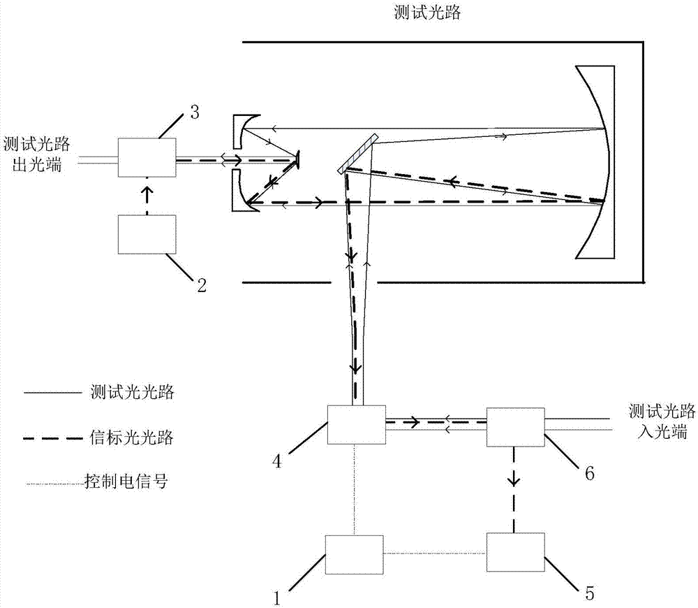
[0017] Place the piezoelectric ceramic fast mirror, the second beam splitter, and the shake detection camera at the light input end of the test light path; place the beacon light source and the first beam splitter at the light output end of the test light path. The installation method is shown in the figure. Turn on the beacon light source and adjust the optical path so that the beacon light passes through the piezoelectric ceramic fast mirror and is mounted on the shake detection camera without affecting the test optical path.

[0018] Adjust the energy of the beacon light so that the energy received by the shake detection camera is appropriate. Use the jitter detection camera to measure the jitter of the beacon light entering from the light exit of the test light path at this time, and the jitter form is the form of jitter existing in the test light path.

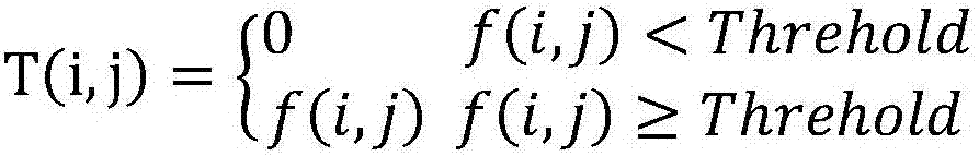
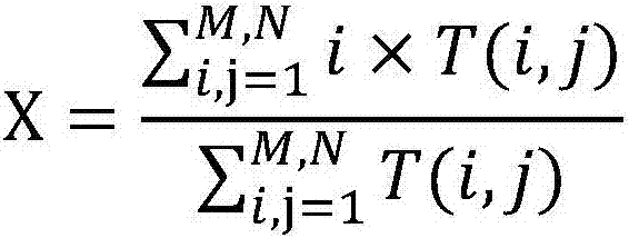
[0019] The light spot of the test beacon light source is collected by the shake detection camera, and the off-target a...


PUM


Abstract

The invention discloses a device and method for actively suppressing the jitter of a test optical path. The active suppression test optical path jitter device is composed of a beacon light, a beam splitter, a piezoelectric fast mirror, and a control computer. The overall method is to emit beacon light at the detection end of the test optical path, use an optical splitter to couple and incorporate the test light, and reversely transmit it to the light input end of the test optical path in the test optical path. A piezoelectric fast mirror, a beam splitter and a detection camera are installed at the light incident end of the test light path. The beacon light is separated into the test light by the beam splitter, and the spot jitter is collected by the detection camera, which is the test light path jitter. The control computer uses the centroid algorithm to calculate the off-target amount of the beacon light and controls the vibration compensation of the piezoelectric fast mirror. The invention can effectively suppress the jitter caused by the platform and the like in the test light path.

Description

technical field [0001] The invention relates to a method for suppressing optical path vibration, in particular to an active suppression method for testing optical path vibration under complex test conditions, which can be used in cross-platform optical path construction, testing and adjustment. Background technique: [0002] In the actual adjustment of optical precision equipment such as large collimator for high-precision testing, the test equipment and the optical path are usually not guaranteed to be on the same platform, and small vibrations on the ground will have a greater impact. For a large device under test, the heavy weight of the device will also cause slight jitter on the platform. This type of jitter is intolerable for high-precision measurement, and certain measures need to be taken to suppress the jitter. [0003] At present, the commonly used jitter suppression measures mostly act on the optical equipment installation platform. This method has high cost, com...

Claims


Application Information

Patent Timeline
IPC IPC(8): G01M11/00G01M11/02
Inventor 贾建军张子玄吴金才张亮强佳
Owner SHANGHAI INST OF TECHNICAL PHYSICS - CHINESE ACAD OF SCI
Why Eureka
Try Eureka