Transverse flux reciprocating motor and reciprocating compressor having a transverse flux reciprocating motor

A transverse magnetic flux, reciprocating technology, applied in the direction of mechanical equipment, machines/engines, liquid variable capacity machinery, etc., can solve the problems of increased power consumption, reduced motor efficiency, complex motor structure, etc., to reduce the number of air gaps and size, reduction of friction loss and noise, and miniaturization of the overall size

Active Publication Date: 2018-01-05
LG ELECTRONICS INC
View PDF9 Cites 3 Cited by
  • Summary
  • Abstract
  • Description
  • Claims
  • Application Information

AI Technical Summary

Problems solved by technology

[0009] However, as mentioned above, for the above-mentioned existing reciprocating motor, hundreds of iron cores are punched out one by one and then stacked radially to manufacture the inner stator or the outer stator. In this method, not only is it difficult to Hundreds of iron cores are punched out and stacked radially, and it is difficult to fix them in a cylindrical shape, so there are considerable difficulties in manufacturing the inner stator and the outer stator
[0010] That is, since hundreds of iron cores need to be punched out to manufacture, high manufacturing costs are incurred, and single iron cores need to be stacked radially, so that the assembly process is difficult to understand and excessive assembly is required time, so there is also the problem of increased manufacturing costs
In addition, even when the single iron cores are bundled in a fixed number and stacked into a plurality of core blocks, and then the core blocks are stacked radially, hundreds of cores still need to be punched out to manufacture, and The inner stator needs to stack individual iron cores radially, so there are still problems in terms of the assembly process for assembling the stator and the manufacturing cost required for this.
[0011] In addition, in the conventional reciprocating motor, in order to fix the inner stator and the outer stator while maintaining the cylindrical shape, an additional fixing ring is press-fitted. The positions of the fixing grooves of the iron cores are aligned and stacked, and it is difficult to press and fix the fixing rings into the fixing grooves provided on hundreds of iron cores
In addition, when forming a magnetic core block by bundling a plurality of iron cores, the shape of these magnetic core blocks is usually maintained by caulking. However, when the area of ​​the core is narrow, during the caulking operation, The shape of part of the iron core may be twisted and deformed, so it is impossible to form the iron core smaller, which limits the miniaturization of the motor
[0012] In addition, for the existing reciprocating motor, the rotor is supported by a mechanical resonance spring composed of a compression coil spring, but due to the self-resonance generated by the characteristics of the compression coil spring, it has: even in a certain range of operating frequency The problem that a specific section within the
[0013] In addition, for the existing reciprocating motor, with the installation of a mechanical resonance spring composed of a compression coil spring, there will be restrictions on the mechanical stress limit and vibration distance in the characteristics of the compression coil spring. This resonance spring needs to ensure a certain wire diameter and length, etc., so there is a limit to reducing the lateral length of the reciprocating motor
[0014] In addition, for existing reciprocating motors, with the installation of mechanical resonance springs composed of compression coil springs, it is necessary to provide spring support members for fixing both ends of the compression coil springs on the rotor and stator, respectively. Therefore, not only the structure of the motor It becomes complicated, and it is necessary to pressurize multiple resonance springs with high pressure and install them on the front and rear sides of the rotor respectively, so there is also a problem that the assembly process becomes difficult.
[0015] In addition, for the conventional reciprocating motor, with the installation of a mechanical resonance spring composed of a compression coil spring, the rotor is eccentric by the side force generated by the characteristics of the compression coil spring, and at the same time, the friction loss between the rotor and the stator is reduced. additional questions
[0016] In addition, in the conventional reciprocating motor, the rotor including the magnet is reciprocally disposed between the outer stator and the inner stator, thereby forming air gaps on the outer side and the inner side based on the rotor, while increasing the air gap. Integral air gap, which reduces the efficiency of the motor
[0017] In addition, for existing reciprocating motors, there is also the fact that the thickness of the magnet frame for supporting the magnets is large, which increases the overall weight of the rotor, thereby not only increasing power consumption, but also reducing the air gap between the outer stator and the inner stator. Further increase, so that the problem of further reduction in motor efficiency occurs
[0018] In addition, the reciprocating compressor to which the above-mentioned reciprocating motor is applied not only still has the problem of the above-mentioned reciprocating motor, but also is restricted in the aspect of miniaturization of the reciprocating compressor due to this problem.

Method used


Image

  • Transverse flux reciprocating motor and reciprocating compressor having a transverse flux reciprocating motor
  • Transverse flux reciprocating motor and reciprocating compressor having a transverse flux reciprocating motor
  • Transverse flux reciprocating motor and reciprocating compressor having a transverse flux reciprocating motor

Examples


Embodiment Construction

[0086] Hereinafter, the transverse flux type reciprocating motor of the present invention will be described in detail based on an embodiment shown in the drawings.

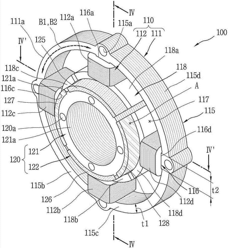
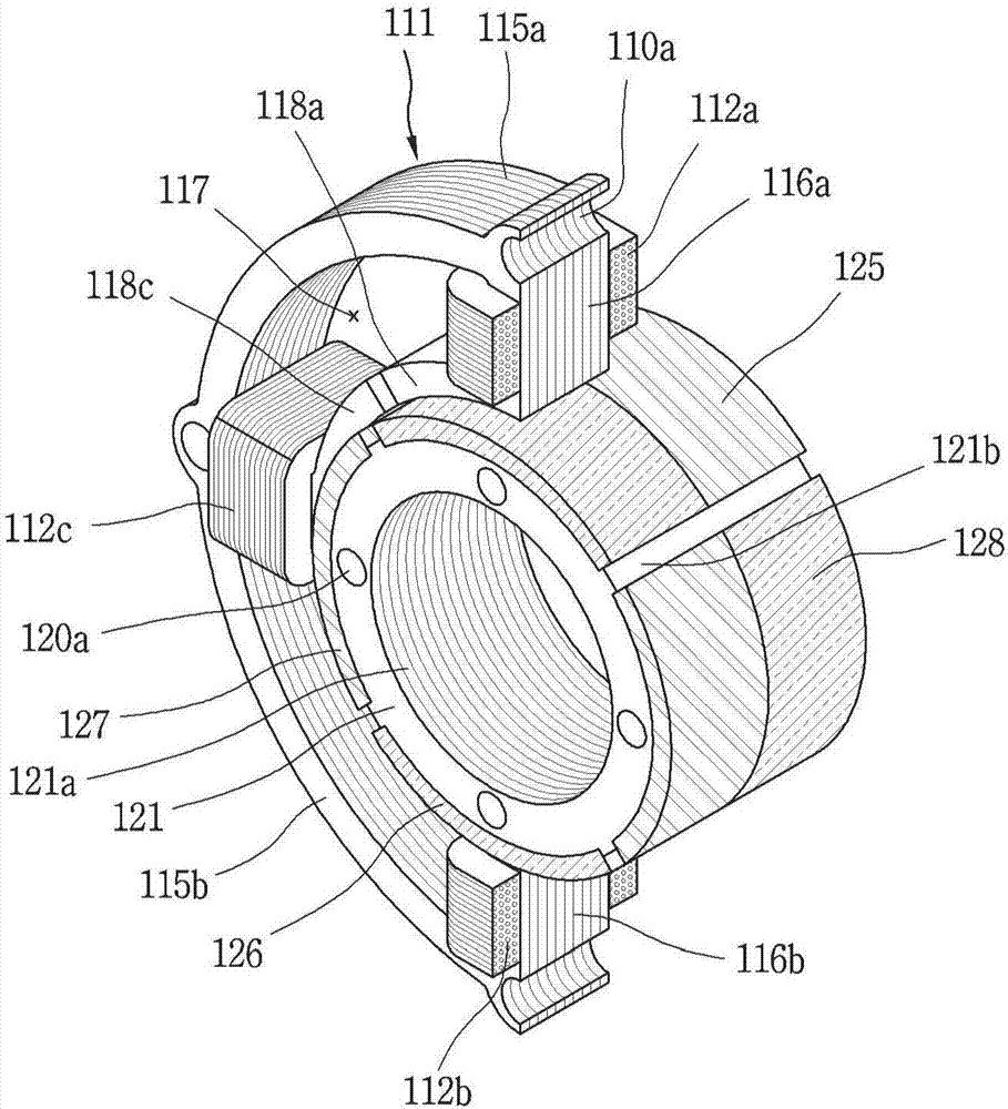
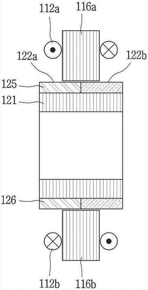
[0087] figure 1 It is a perspective view showing an embodiment of the transverse flux type reciprocating motor of the present invention; figure 2 will be figure 1 A perspective view showing a part of the transverse flux type reciprocating motor cut away; Figure 3A and Figure 3B are along figure 1 Sectional view of line IV-IV and line IV'-IV'; Figure 4 yes means figure 1 The front view of the transverse flux flux compound motor; Figure 5A , Figure 5B and Figure 5C is used to explain the action of the reciprocating motor of this embodiment, along Figure 4 A schematic diagram of the Ⅴ-Ⅴ line.

[0088] Such as figure 1 As shown, the transverse flux type reciprocating motor (hereinafter simply referred to as the reciprocating motor) 100 of this embodiment is configured by inserting the rotor 120 insi...


PUM


Abstract

A transverse flux reciprocating motor and a reciprocating compressor having a transverse flux reciprocating motor are provided. The transverse flux reciprocating motor may include a stator wound witha magnet coil, a mover inserted into the stator and coupled with a magnet having opposite magnetic poles in an orthogonal direction with respect to a magnetic flux generated by the magnet coil, and aresonance spring that allows the mover to perform a resonance motion with respect to the stator using a force trying to move toward a side with low magnetic resistance between the stator and the mover, whereby the transverse flux reciprocating motor and the reciprocating compressor having a transverse flux reciprocating motor may be reduced in size and weight and obtain high efficiency.

Description

technical field [0001] The present invention relates to a reciprocating motor and a reciprocating compressor having the same, in particular to a transverse flux type reciprocating motor in which the direction of flux (Flux) forms a right angle to the moving direction of a rotor and a reciprocating compressor having the same. Background technique [0002] Motor (Motor) is a device that obtains rotational force or reciprocating power by converting electrical energy into mechanical energy. Such motors can be divided into AC motors and DC motors according to the type of power applied. [0003] The motor includes a stator (Stator) and a rotor (Mover or Rotor). Along the direction of the magnetic flux (Flux) generated when the current passes through the coil (Coil) set on the stator, the rotor with a magnet (Magnet) rotates or reciprocating motion. [0004] Depending on how the rotor moves, motors can be classified as rotary or reciprocating. A rotary motor is a method in which ...

Claims


Application Information

Patent Timeline
Patent Type & Authority Applications(China)
IPC IPC(8): H02K33/00H02K1/14H02K1/34
CPCF04B35/045H02K33/16H02K2201/12F04B35/04F04B39/0005F04B39/121F04B53/10H02K1/146H02K1/34H02K33/00
Inventor 郑相燮金在范朴贞植李秀硕
Owner LG ELECTRONICS INC
Why Eureka
Try Eureka