Method and device for charging control of hay mower
A charging control method and lawn mower technology, applied to circuit devices, battery circuit devices, harvesters, etc., can solve the problems of excessive battery power, lawn mower charging, low use efficiency, etc., and improve power use efficiency Effect
- Summary
- Abstract
- Description
- Claims
- Application Information
AI Technical Summary
Problems solved by technology
Method used
Image
Examples
Embodiment 1
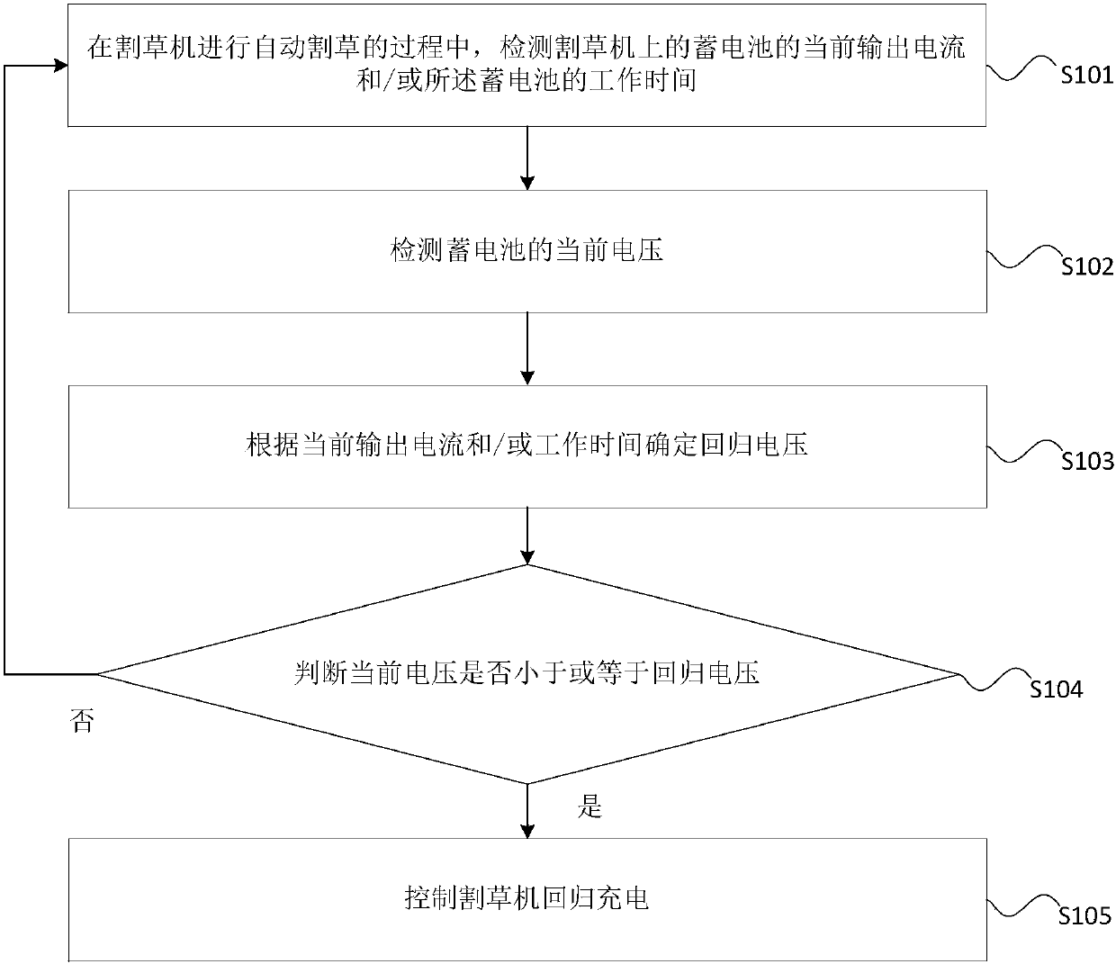
[0032] This embodiment provides a charging control method for a lawn mower, which can be used on a controller of a lawn mower, such as figure 1 As shown, the method includes:
[0033] Step S101, in the process of automatic mowing by the lawnmower, the current output current of the battery on the lawnmower and / or the working time of the battery are detected.
[0034] Step S102, detecting the current voltage of the battery.
[0035] In this embodiment, after the lawnmower starts the automatic mowing program, and during the automatic mowing process, the current output current and / or working time of the battery can be detected in real time, and the current voltage can be detected in real time.
[0036] Step S103, determining the return voltage according to the current output current and / or the working time.
[0037] Step S104, it is determined whether the current voltage is less than or equal to the return voltage.
[0038] Step S105, when the current voltage is less than or eq...
Embodiment 2
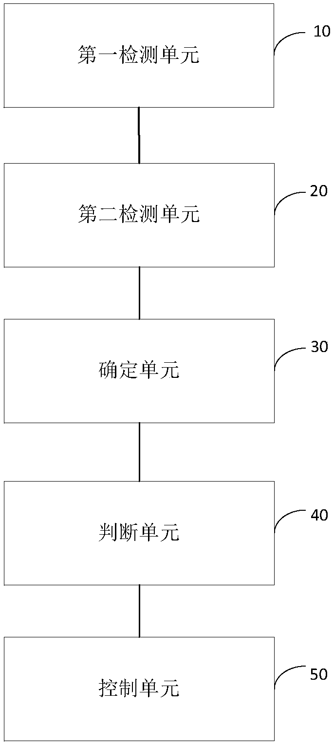
[0072] This embodiment provides a charging control device for a lawn mower, and the device can be used to execute the charging control method for a lawn mower according to Embodiment 1 of the present invention, such as figure 2 As shown, the device includes: a first detection unit 10 , a second detection unit 20 , a determination unit 30 , a judgment unit 40 and a control unit 50 .
[0073] The first detection unit 10 is used to detect the current output current of the battery on the lawnmower and / or the working time of the battery during the automatic mowing of the lawnmower; the first detection unit 10 is also used to detect when the current voltage does not reach When returning to voltage, recheck the output current and / or operating time on the mower;
[0074] The second detection unit 20 is used for the current voltage of the battery;
[0075] In this embodiment, after the lawnmower starts the automatic mowing program, and during the automatic mowing process, the current...
Embodiment 3
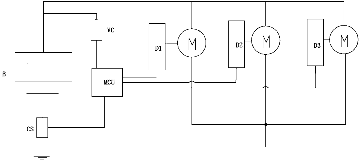
[0105] This embodiment provides a charging control circuit, such as image 3 As shown, the control circuit includes a micro control unit MCU, a voltage detection circuit VC, and a current detection circuit CS, wherein the voltage detection circuit VC is used to detect the voltage of the battery B, and the current detection circuit CS is used to detect the output current of the battery B. The micro control unit MCU in the embodiment is also used to control the driving circuit of the motor M (including the driving circuit D1 , the driving circuit D2 and the driving circuit D3 ).
[0106] Those skilled in the art should understand that the embodiments of the present invention may be provided as methods, systems, or computer program products. Accordingly, the present invention can take the form of an entirely hardware embodiment, an entirely software embodiment, or an embodiment combining software and hardware aspects. Furthermore, the present invention may take the form of a com...
PUM
 Abstract
Description
Claims
Application Information
 - R&D
- Intellectual Property
- Life Sciences
- Materials
- Tech Scout
- Unparalleled Data Quality
- Higher Quality Content
- 60% Fewer Hallucinations
Browse by: Latest US Patents, China's latest patents, Technical Efficacy Thesaurus, Application Domain, Technology Topic, Popular Technical Reports.
© 2025 PatSnap. All rights reserved.Legal|Privacy policy|Modern Slavery Act Transparency Statement|Sitemap|About US| Contact US: help@patsnap.com


