Trigger resistance providing method, trigger structure and game device

A game device and trigger technology, applied in the field of trigger resistance, trigger structure and game device, can solve the problems of limited assembly space, inconvenient operation, space occupation, etc., meet the requirements of reducing assembly space, simple and convenient assembly process, and reduce production cost effect

Active Publication Date: 2018-01-09
GEER TECH CO LTD
View PDF7 Cites 9 Cited by
  • Summary
  • Abstract
  • Description
  • Claims
  • Application Information

AI Technical Summary

Problems solved by technology

[0004] The disadvantage of the silicone pad driving method is that the silicone pad will be damaged and invalidated as the number of times of use increases, and the silicone pad needs to be replaced regularly, which increases the cost
[0005] The disadvantages of the torsion spring driving method are: (1) The assembly space is limited, preloading is required during assembly, the assembly process is more complicated, and the operation is inconvenient
(2) It needs to occupy a certain space, and the structural design is relatively limited
(3) Damage and failure occur as the number of uses increases

Method used


Image

  • Trigger resistance providing method, trigger structure and game device
  • Trigger resistance providing method, trigger structure and game device
  • Trigger resistance providing method, trigger structure and game device

Examples


Embodiment 1

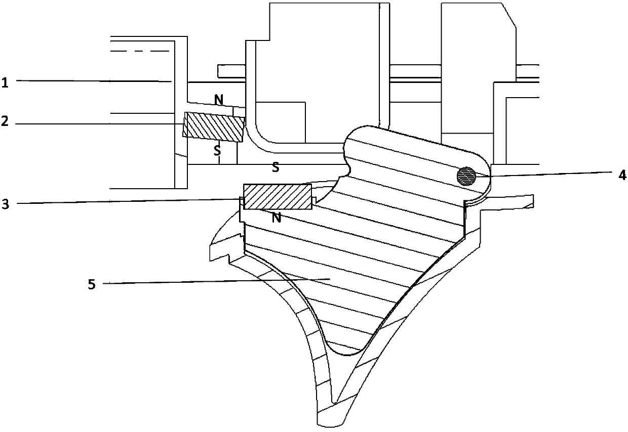
[0026] figure 1 It is a schematic diagram of a trigger structure of an embodiment of the present invention, such as figure 1 As shown, the trigger structure includes a main bracket 1, a trigger assembly 5 and a trigger shaft 4, and the trigger structure claimed in this application also includes a first magnet group 2 and a second magnet group 3;

[0027] The first magnet group 2 is arranged on the main bracket 1, and the second magnet group 3 is arranged on the trigger assembly 5;

[0028] When the trigger assembly 5 rotates around the trigger shaft 4, the distance between the first magnet group 2 and the second magnet group 3 changes, and the repulsive force between the first magnet group 2 and the second magnet group 3 also changes accordingly. The change in repulsive force provides trigger resistance.

[0029] It should be noted that when the trigger assembly 5 rotates to the maximum stroke (that is, the trigger rotates to the lowest point), the distance between the first...

Embodiment 2

[0040] Figure 4 is a schematic diagram of a game device according to an embodiment of the present invention, such as Figure 4 as shown,

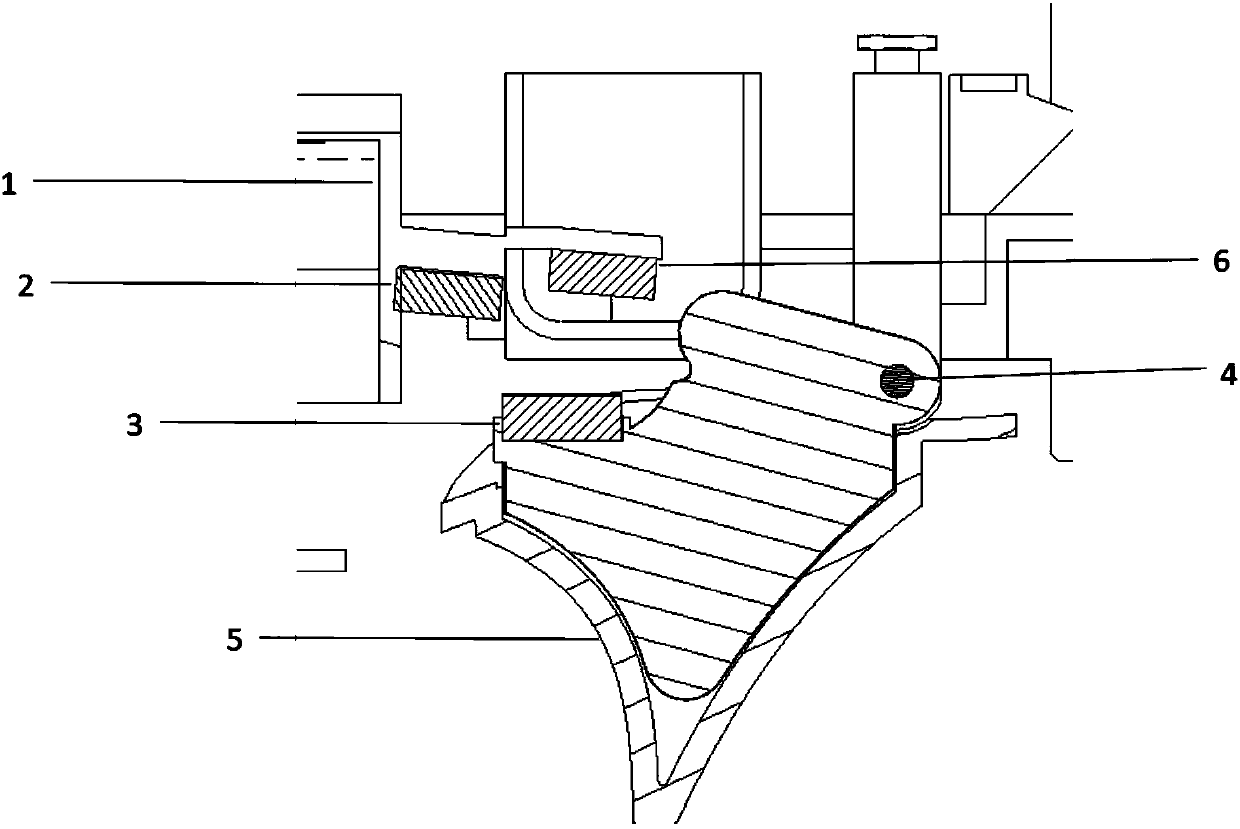
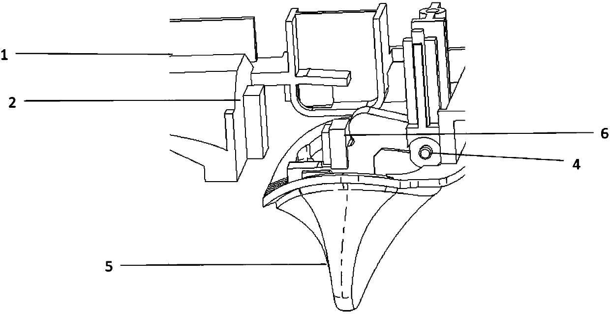
[0041] game devices include figure 1 or figure 2 or image 3 Trigger structure shown.

[0042] In one embodiment of the invention, the gaming device may be a joystick.

Embodiment 3

[0044] Figure 5 is a flowchart of a method for providing trigger resistance in an embodiment of the present invention, such as Figure 5 as shown,

[0045] In step S110, a first magnet group is set on the main bracket of the trigger, and a second magnet group is set on the trigger assembly of the trigger;

[0046] In step S120, when the trigger assembly rotates around the trigger shaft, the distance between the first magnet group and the second magnet group changes, and the repulsive force between the first magnet group and the second magnet group also changes accordingly. The change in force provides trigger resistance.

[0047] In one embodiment of the present invention, the centers of the first magnet group and the second magnet group are arranged in the same vertical plane.

[0048] In one embodiment of the present invention, the magnetic properties of the first magnet group and the second magnet group are set so that when the trigger assembly is in the initial positi...


PUM


Abstract

The invention discloses a trigger resistance providing method, a trigger structure and a game device. The trigger structure comprises a main support, a trigger component, a trigger rotating shaft, a first magnet set and a second magnet set. The first magnet set is arranged on the main support, and the second magnet set is arranged on the trigger component. When the trigger component rotates aroundthe trigger rotating shaft, the distance and the repelling force between the first magnet set and the second magnet set are changed, and trigger resistance is provided by change of the repelling force. Compared with the prior art, the trigger structure is simplified, the requirement of assembly space is reduced, the assembly process is simple and convenient, and the working efficiency of an assembly engineer can be improved. As the trigger resistance is provided by the repelling force between the magnets, the magnetic force of the magnets cannot be attenuated along with increase of use frequency, the service life is long, periodic replacement of the magnets is omitted, and production cost is reduced.

Description

technical field [0001] The invention relates to the field of game control devices, in particular to a method for providing trigger resistance, a trigger structure and a game device. Background technique [0002] The trigger is a key part of the gamepad, and the strength in the game can be realized by rotating the trigger. In the process of rotating the trigger, there needs to be a feeling of damping, and it is required that as the rotation stroke becomes larger, the feedback force of the trigger should also increase accordingly, so as to give customers a better hand feeling experience. At the same time, when the user releases the trigger, it needs to forcefully drive the trigger to automatically return to the initial position. [0003] At present, there are mainly two ways to drive the trigger, one is to drive the trigger through an elastic silicone pad, and the other is to drive the trigger through a torsion spring. Although these two trigger driving methods can produce a...

Claims


Application Information

Patent Timeline
Patent Type & Authority Applications(China)
IPC IPC(8): A63F13/219A63F13/24
Inventor 盛希龙李晓东
Owner GEER TECH CO LTD
Why Eureka
Try Eureka