Eureka AIR delivers breakthrough ideas for toughest innovation challenges, trusted by R&D personnel around the world.

Film shaking dust remover

A film sheet and dust collector technology, which is applied in the fields of static electricity, electrical components, cleaning methods and utensils, etc., can solve the problems of poor electrostatic removal effect of dust, difficult modularization of each functional block, and complicated assembly of the shaking device. The effect of up and down jitter amplitude, simple assembly, and low equipment cost

Pending Publication Date: 2018-01-09
东莞市朗烁自动化设备有限公司
View PDF8 Cites 5 Cited by
  • Summary
  • Abstract
  • Description
  • Claims
  • Application Information

AI Technical Summary

Problems solved by technology

[0006] Although the technical solution disclosed in the above-mentioned 201420806386.0 patent has solved the existing technical problems well, it has the following shortcomings: first, the above-mentioned material shaking device uses a conveyor belt for diaphragm transmission, and the dust of the material shaking and dedusting is easy to fall back and It sticks to the film sheet and the transmission belt again, causing secondary pollution; second, the electrostatic dust removal of the above-mentioned shaker device uses an ion fan, which has a poor effect of removing dust and static electricity, and is only installed on the upper end of the shaker line, which is unreasonable The third is that the assembly of the above-mentioned shaking device is complicated, and each functional block is not easy to be modularized

Method used


Image

  • Film shaking dust remover
  • Film shaking dust remover
  • Film shaking dust remover

Examples


Embodiment Construction

[0031] The present invention will be described in further detail below in conjunction with the accompanying drawings.

[0032]The embodiments described by referring to the figures are exemplary and are intended to explain the present application and should not be construed as limiting the present application. In the description of the present application, it should be understood that the terms "center", "longitudinal", "transverse", "length", "width", "thickness", "upper", "lower", "front", " Orientation or position indicated by "back", "left", "right", "vertical", "horizontal", "top", "bottom", "inner", "outer", "clockwise", "counterclockwise", etc. The relationship is based on the orientation or positional relationship shown in the drawings, and is only for the convenience of describing the application and simplifying the description, rather than indicating or implying that the referred device or element must have a specific orientation, be constructed and operated in a spec...


PUM


Abstract

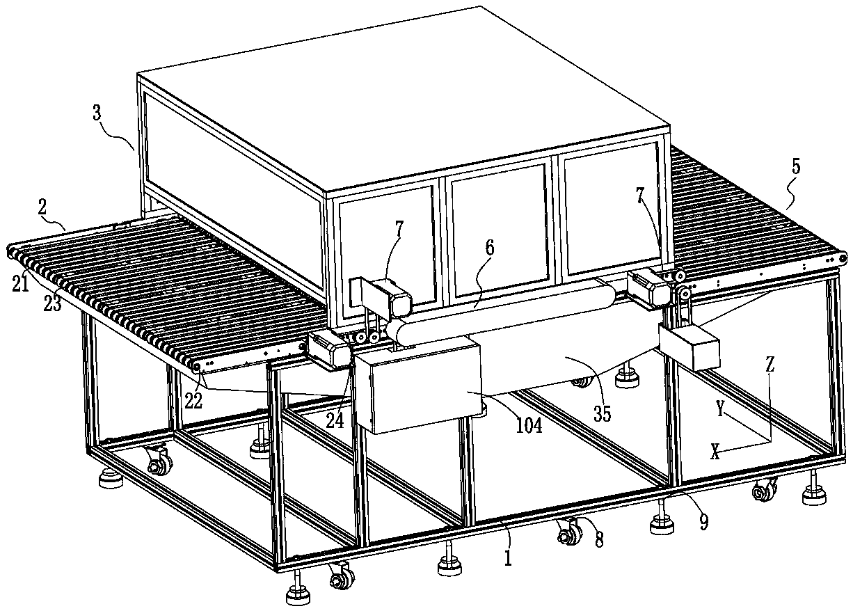
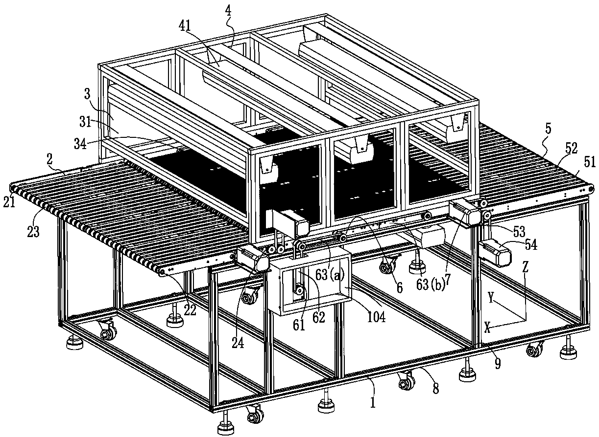
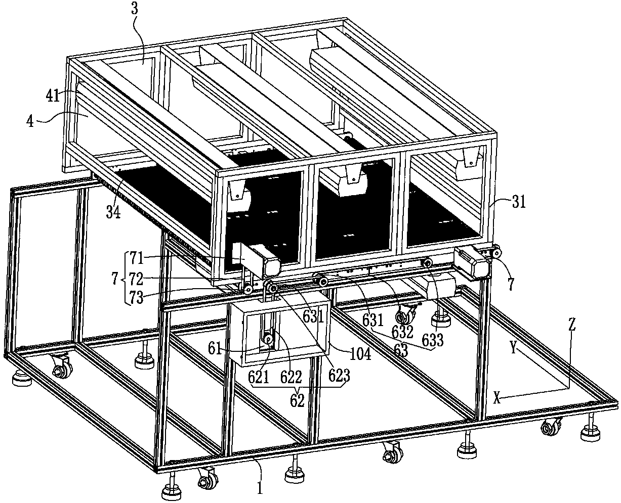
The invention discloses a film shaking dust remover. The film shaking dust remover comprises a frame, a loading module, a shaking module, an electrostatic dust removing module and a collecting module;the loading module is arranged beside the transverse direction of the frame, and is used for conveying films to the shaking module; the shaking module is in butt joint with the loading module, and comprises a shaking box; two transmission rollers are transversely arranged in the shaking box at intervals, and are in transmission connection through multiple strip-shaped shaking lines radially arranged at intervals; at least one transmission roller is connected with a transmission device; at least two shaking rotary modules are arranged between the two transmission rollers; all the shaking rotary modules are embedded in the multiple shaking lines, and are driven to synchronously rotate through driving modules, so that the multiple shaking lines are synchronously shaken up and down to bump the films; the electrostatic dust removing module comprises multiple ion air rods; the multiple ion air rods are arranged in the shaking box, and are symmetrically arranged up and down relative to the shaking lines for removing static electricity of dust; and the collecting module is arranged on the other transverse side of the frame, is in butt joint with the shaking module, and is used for conveying and unloading the electrostatic-dedusted films.

Description

technical field [0001] The invention relates to the technical field of waste discharge equipment and devices, in particular to a thin film shaker and dust remover. Background technique [0002] Optical films are ubiquitous in our lives, from precision and optical equipment, display equipment to optical film applications in daily life, such as eyes, digital cameras, various home appliances, or anti-counterfeiting technology on banknotes. This is called the extension of the application of optical thin film technology. Without optical thin film technology as the basis for development, modern photoelectric, communication or laser technology will not be able to make progress, which also shows the importance of research and development of optical thin film technology. [0003] Optical films are cut into optical films of different sizes or shapes for different occasions, and the films need to be cleaned before application. There will be impurities on the optical films, which are g...

Claims


Application Information

Patent Timeline
Patent Type & Authority Applications(China)
IPC IPC(8): B08B7/02H05F3/06
Inventor 胡建平
Owner 东莞市朗烁自动化设备有限公司
Why Eureka
Eureka Blog
Learn More