Motor protection type electric-controlled brake booster

A technology for electronically controlled braking and motor protection, applied in the direction of brakes, brake transmissions, vehicle components, etc., can solve the problems of increasing product development costs, unable to protect the motor from waterproofing, increasing the motor damage rate, etc., to reduce the space layout and the complexity of the system, the effect of reducing the modification of parts and extending the service life

Pending Publication Date: 2018-01-09
GELUBO TECH CO LTD
View PDF10 Cites 2 Cited by
  • Summary
  • Abstract
  • Description
  • Claims
  • Application Information

AI Technical Summary

Problems solved by technology

This type of electronically controlled brake booster needs to develop the motor and motor accessories separately, instead of using the batch brushless DC motors that are already on the market, which greatly increases the cost of product development
[0010] At the same time, most of the existing traditional motors are directly exposed on the outer surface, which cannot effectively protect the motor from waterproofing, which greatly increases the damage rate of the motor

Method used


Image

  • Motor protection type electric-controlled brake booster
  • Motor protection type electric-controlled brake booster
  • Motor protection type electric-controlled brake booster

Examples


Embodiment Construction

[0029] The implementation of the present invention will be illustrated by specific specific examples below, and those skilled in the art can easily understand other advantages and effects of the present invention from the contents disclosed in this specification.

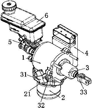
[0030] Such as figure 1 Shown is a schematic diagram of the overall structure of the present invention, an electronically controlled brake booster, including a motor 2, a transmission mechanism, a pedal input mechanism 3, a housing assembly 1, an electronic control unit 4, a brake master cylinder 5 and a liquid storage tank 6. The pedal input mechanism 3 is fixedly installed at the rear end of the housing assembly 1, the motor 2 is fixedly installed at the lower end of the housing assembly 1, the brake master cylinder 5 is fixedly installed at the front end of the housing assembly 1, and the brake master The other end of the cylinder 5 is also fixedly installed with a liquid storage tank 6 , and the transmission mec...


PUM


Abstract

The invention discloses a motor protection type electric-controlled brake booster, which comprises an electric motor, a driving mechanism, a pedal input mechanism, a shell body component, an electronic control unit, a main brake cylinder and a fluid storage tank; the pedal input mechanism is fixedly installed at the back end part of the shell body component, and the electric motor is fixedly installed at the lower end part of the shell body component; the main brake cylinder is further fixedly equipped with one fluid storage tank, and the driving mechanism is fixedly installed at the inner endpart of the shell body component. Through sheathing an annular motor cover on the outer surface of the electric motor and coating glue water to the joint between the motor cover and the shell body component or sealing by a rubber ring, while sealing the joint between the annular motor cover and the motor by the rubber ring also, the waterproof measure of the motor is effectively realized, the using environment requirement of arranging the booster assembly at an engine cabin is satisfied, and the service life of the motor is prolonged.

Description

technical field [0001] The invention belongs to the field of automobile brake boosters, in particular to a motor protection type electric control [0002] brake booster. Background technique [0003] Most traditional automobile brake boosters are in the form of vacuum boosters. The traditional car braking system is mostly hydraulic. The driver steps on the brake pedal, pushes the pedal input rod to push the brake master cylinder, and the vacuum booster also applies the brake boost to the pedal input rod at the same time. The active master cylinder produces axial thrust. The brake master cylinder and the brake caliper piston cavity of the four wheels are equivalent to a connector structure. The hydraulic pressure of the master cylinder is transmitted to the wheel cylinder basically without loss, and the piston at the end moves axially to clamp the brake disc to generate braking force. [0004] When the hydraulic brake system is used, the force of the driver stepping on the...

Claims


Application Information

Patent Timeline
Patent Type & Authority Applications(China)
IPC IPC(8): B60T13/74
Inventor 张磊罗强
Owner GELUBO TECH CO LTD
Why Eureka
Try Eureka