Eureka AIR delivers breakthrough ideas for toughest innovation challenges, trusted by R&D personnel around the world.

Bionic flapping-wing aircraft based on flapping-folding-torsion coupling movement

A flapping-wing aircraft and coupled motion technology, applied in the field of bionic flapping-wing aircraft, can solve the problems of many driving moving parts, offset of lift and drag, complex structure, etc., and achieve less driving moving parts, light structure weight and high flight capability Good results

Inactive Publication Date: 2018-01-09
WUHAN UNIV OF SCI & TECH
View PDF8 Cites 21 Cited by
  • Summary
  • Abstract
  • Description
  • Claims
  • Application Information

AI Technical Summary

Problems solved by technology

At present, most of the flapping-wing aircraft studied are single-degree-of-freedom mechanisms or multi-drive multi-degree-of-freedom mechanisms. The flight mode of single-degree-of-freedom mechanisms is simple, and the flight flexibility and stability cannot be compared with flying creatures. The structure of wing aircraft is complex, there are many driving parts, and the control system is complex
The patent (CN102211665A) adopts a single-degree-of-freedom flapping wing movement, and there are two pairs of flapping wings at the front and rear, but the upward and downward flapping are symmetrical, and the generated lift and drag are offset, so no effective lift can be generated.
Patent (CN201610408704.1) discloses a multi-degree-of-freedom bird-like flapping wing aircraft, which adopts multi-degree-of-freedom flapping wing movement. Although it can realize multi-degree-of-freedom movement, it has many driving parts and high mass

Method used


Image

  • Bionic flapping-wing aircraft based on flapping-folding-torsion coupling movement
  • Bionic flapping-wing aircraft based on flapping-folding-torsion coupling movement
  • Bionic flapping-wing aircraft based on flapping-folding-torsion coupling movement

Examples


Embodiment Construction

[0026] Below in conjunction with accompanying drawing, the present invention is illustrated

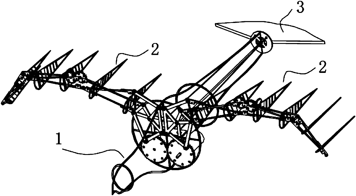
[0027] Such as figure 1 As shown, a bionic flapping-wing aircraft based on flapping-folding-twisting coupling motion is composed of a fuselage 1, an empennage mechanism 3 and wings 2 located on both sides of the fuselage 1, the fuselage 1 Including the outer frame of the fuselage and the wing fixing frame 101 fixedly installed in the middle part of the outer frame of the fuselage;

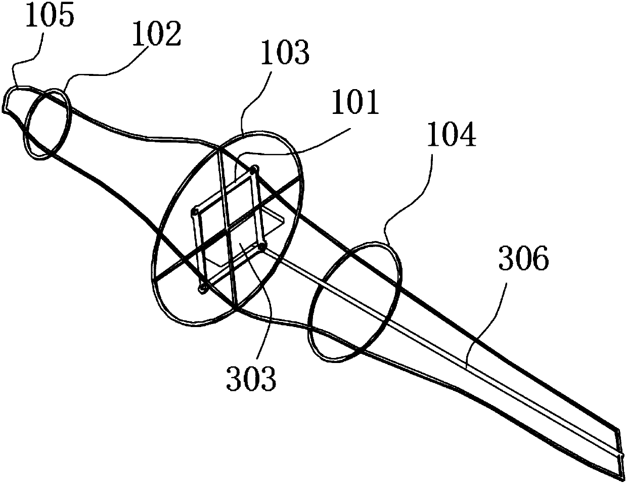
[0028] Such as figure 2 As shown, the entire outer frame of the fuselage is a bird-like shape, and the outer frame of the fuselage is composed of a front section circular frame 102, a middle section circular frame 103 and a rear section circular frame 104 connected by a vertical frame 105 in turn.

[0029] Such as Figure 4 , Figure 5 with Figure 6As shown, the wing 2 includes a front section wing 201, a middle section wing 202, a terminal section wing 203, and a soft cladding layer coated on the t...


PUM


Abstract

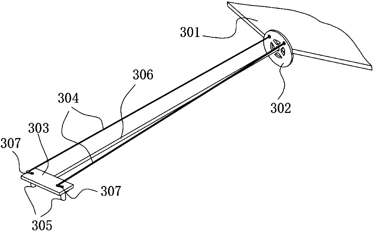
The invention discloses a bionic flapping-wing aircraft based on flapping-folding-torsion coupling movement. The bionic flapping-wing aircraft is composed of a fuselage, wings on the two sides and anempennage mechanism. When a wing motor is started, a crank gear on an output shaft of the wing motor rotates to sequentially drive first front-section wing rods, second front-section wing rods and third front-section wing rods to rotate, and the flapping movement of the wings is achieved; fixed gears swing up and down along with the second front-section wing rods to transmit the torque to driven bevel gears through planet gears, so that third wing face supporting plates rotate within a small range around the third front-section wing rods, and accordingly the torsion movement of the wings is achieved; and the flapping angles of front-section wing bodies, middle-section wing bodies and tail-section wing bodies are different, and accordingly the folding movement of the wings is achieved. Steering of the aircraft is achieved jointly through an empennage and a steering engine for adjusting the empennage direction. The bionic flapping-wing aircraft based on the flapping-folding-torsion coupling movement has the characteristics that the number of driving original motive parts is small, the flapping-folding-torsion coupling movement of the flapping wings can be achieved, flying is flexible, and generated effective lift force is large.

Description

technical field [0001] The invention belongs to the technical field of bionic flapping-wing aircraft. In particular, it relates to a bionic flapping-wing aircraft based on flapping-folding-twisting coupling motion. Background technique [0002] Flapping wing flight has good maneuverability and flexibility. Compared with fixed-wing flight, it uses the principle of bionics to imitate the flight characteristics of birds to obtain high lift and has high flight stability. Compared with the single-degree-of-freedom flapping-wing movement, the multi-degree-of-freedom flapping-wing movement can better realize the attitude of flying creatures, the flight is flexible, and the flight mode can be better controlled during the movement. At present, most of the flapping-wing aircraft studied are single-degree-of-freedom mechanisms or multi-drive multi-degree-of-freedom mechanisms. The flight mode of single-degree-of-freedom mechanisms is simple, and the flight flexibility and stability c...

Claims


Application Information

Patent Timeline
Patent Type & Authority Applications(China)
IPC IPC(8): B64C33/02
Inventor 华兆敏侯宇屠凯杨书建
Owner WUHAN UNIV OF SCI & TECH
Why Eureka
Eureka Blog
Learn More