
Steel structure bridge pavement expansion joint filling and covering device

A technology of covering devices and expansion joints, which is applied in bridges, bridge parts, bridge construction, etc., can solve the problems of bridge vibration, rubber belt damage, bridge deck water leakage and other problems, so as to prolong the service life, avoid contact extrusion, avoid The effect of excessive deformation

Inactive Publication Date: 2018-01-09
孙杏珍
View PDF0 Cites 1 Cited by
  • Summary
  • Abstract
  • Description
  • Claims
  • Application Information

AI Technical Summary

Problems solved by technology

But it can have the following problems: one, bridge expansion joints need to be repaired and replaced after aging and damage, and most bridges are located on main arterial roads or expressways with large traffic volumes, often blocking traffic due to repairs and replacements. Second, most of the original expansion joints are replaced with steel expansion joints, which is expensive and takes a long time to maintain; Expansion joint concrete is difficult to achieve the ideal strength, the service life is greatly shortened, resulting in a great waste of manpower and funds
[0004] Judging from the use effect of the existing telescopic devices, the sealing effect is not good. Many telescopic devices will have partial damage or overall fracture of the rubber belt after a period of use, resulting in water leakage on the bridge deck in rainy weather, and even bridge failure in rainy weather. The "waterfall" scene, after these conditions continue for a long time, will not only affect the beauty of the bridge, but also cause corrosion of the bridge bearing, affect the durability of the bridge structure, and not only have a negative impact on the bridge itself, but also affect the buildings under the bridge or normal use of the device

Method used


Image

  • Steel structure bridge pavement expansion joint filling and covering device
  • Steel structure bridge pavement expansion joint filling and covering device
  • Steel structure bridge pavement expansion joint filling and covering device

Examples


Embodiment Construction

[0021] The technical solution of this patent will be described in further detail below in conjunction with specific embodiments.

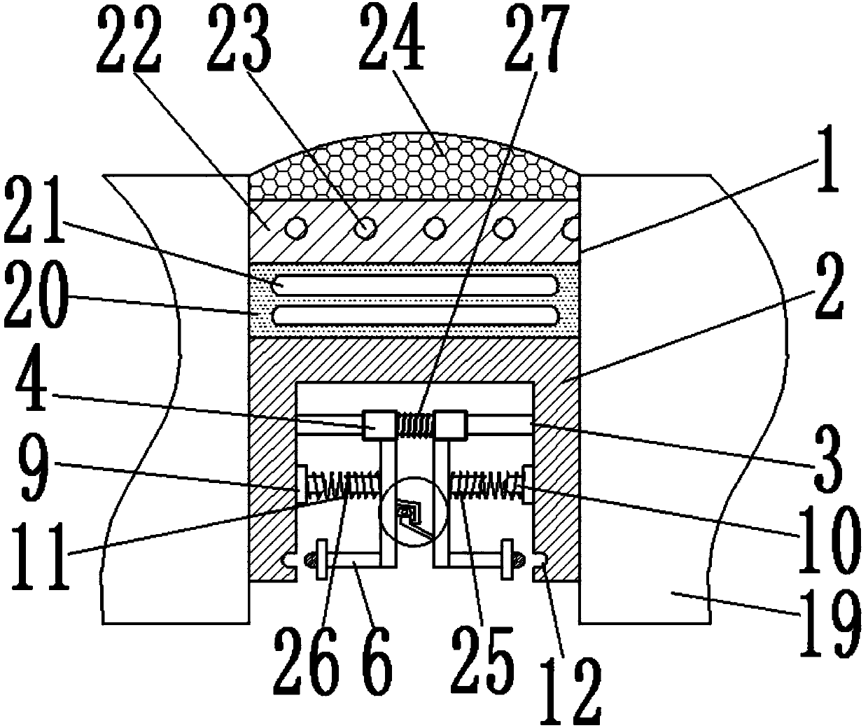
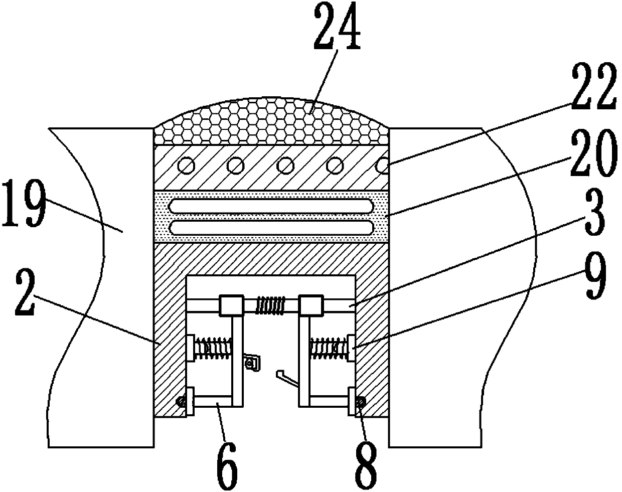
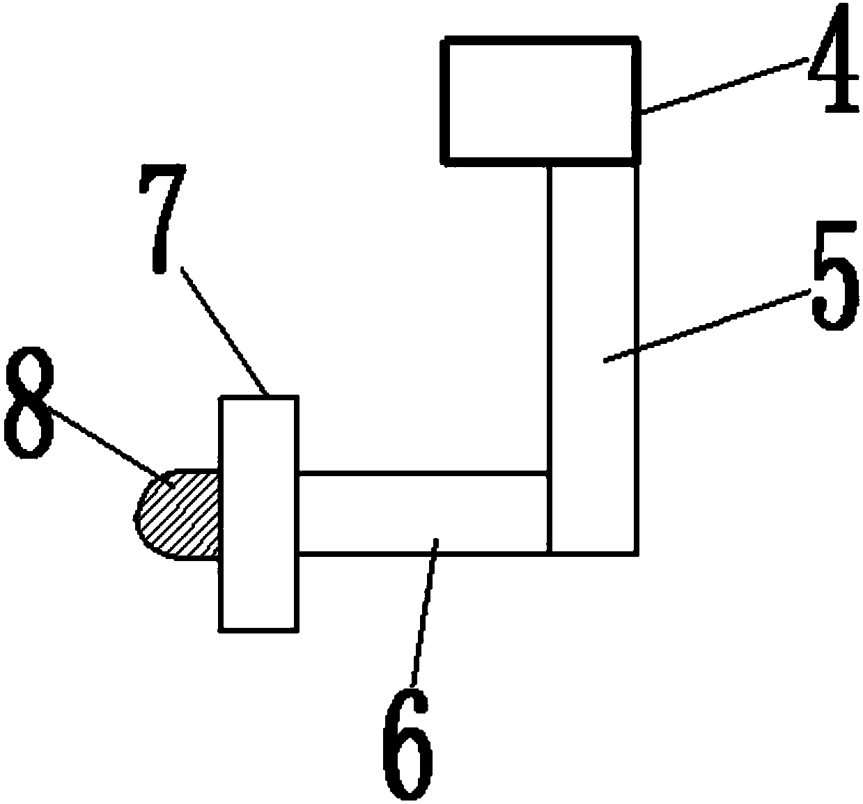
[0022] See Figure 1-4 , A steel structure bridge pavement expansion joint filling and covering device, comprising an expansion joint 1 and a hard rubber base layer 2; the two sides of the expansion joint 1 are a road base 19; the hard rubber base layer 2 is arranged inside the expansion joint 1 The bottom of the hard rubber base layer 2 is an inverted U-shaped structure, with support rods 3 arranged in the grooves; both ends of the support rods 3 are fixed on the two grooves of the hard rubber base layer 2. Two sleeves 4 are arranged on the side inner wall; the lower end of the sleeve 4 is connected with a vertical rod 5; the vertical rod 5 is connected with a cross rod 6 in the direction of the inner wall of the groove of the hard rubber base layer 2; The end of the crossbar 6 is provided with a stopper 7; the front end of the stopper 7 is provided...


PUM


Abstract

The invention provides a filling and covering device for expansion joints of steel structure bridge pavement, which comprises an expansion joint and a hard rubber base; both sides of the expansion joint are pavement substrates; a support rod is arranged in a groove of the hard rubber base; Two bushings are arranged on the support rod; the lower end of the bushing is connected with a vertical rod; the vertical rod is connected with a cross rod; the end of the cross rod is provided with a block; The first elastic rod and the second elastic rod are respectively arranged on the top; the end of the first elastic rod is provided with a lock; the end of the second elastic rod is provided with a lock hook; the upper end of the hard rubber base is filled with High-elastic rubber buffer layer; the upper end of the high-elastic rubber buffer layer is filled with a high-density rubber support layer; the upper end of the high-density rubber support layer is provided with a rubber contact layer; the present invention is simple in structure, easy to use, shear pin and The setting of the shear hole can buffer the pressure between the two walls of the groove of the hard rubber base.

Description

Technical field [0001] The invention relates to the technical field of bridge maintenance equipment, in particular to a steel structure bridge pavement expansion joint filling and covering device. Background technique [0002] A bridge is an open-air permanent structure that crosses obstacles such as rivers, deep valleys, and built roads. Due to the effects of temperature changes, concrete shrinkage and creep, and changing loads, the beam ends of the bridge will experience creep. In order to adapt to the bridge structure With this characteristic, it is necessary to set freely deformable expansion joints between the road surface of the bridge structure and the end of the beam and the back wall of the abutment to ensure the smoothness of the bridge deck and protect the structure. [0003] Expansion joints are used to form the connecting mechanism between the precast concrete parts of the bridge deck. The expansion joints currently used are steel structures. However, there will be th...

Claims


Application Information

Patent Timeline
Patent Type & Authority Applications(China)
IPC IPC(8): E01D19/06E01D19/08
Inventor 孙杏珍刘美芳
Owner 孙杏珍
Learn More