
Layered oil production unidirectional pipe column continuous reversing device and method

A technology of layered oil production and reversing device, which is applied to the valve device of wellbore/well, production fluid, earth-moving drilling and other directions, can solve the problems of increasing benefit, reducing oil production efficiency, increasing difficulty and cost, and saving process. , The effect of shortening the construction period, reducing labor intensity and operating costs

Inactive Publication Date: 2018-01-09
刘玉友
View PDF0 Cites 4 Cited by
  • Summary
  • Abstract
  • Description
  • Claims
  • Application Information

AI Technical Summary

Problems solved by technology

[0002] In oil field production, multi-level is a common phenomenon. In many layers, the oil-water content of liquid is different. In order to improve efficiency, in oil field production, it is necessary to inject ash, water shut-off agent, chemical water shut-off Block the water layer and exploit the oil layer in order to increase the oil recovery rate, reduce the cost, and increase the benefit. For multi-layer oil production, use the bridge plug to block the non-target oil layer in advance, and then use this new technology string to exploit any target layer. , which can seal the unneeded production reservoirs and realize the oil recovery of the target layer of the oil well. At present, the patent number is 2013104715687, and the patent name is "A Layered Oil Production Device". The problem of this device is: the one-way pipe string will produce reverse direction, but it cannot be reset. In actual production, it is necessary to use a pump to pump out the liquid in the pipe string, which cannot realize continuous reversing, which increases the operating cost. Difficulty and expense, reducing the efficiency of oil recovery

Method used


Image

  • Layered oil production unidirectional pipe column continuous reversing device and method
  • Layered oil production unidirectional pipe column continuous reversing device and method
  • Layered oil production unidirectional pipe column continuous reversing device and method

Examples


Embodiment Construction

[0022] The preferred embodiments of the present invention will be described below in conjunction with the accompanying drawings. It should be understood that the preferred embodiments described here are only used to illustrate and explain the present invention, and are not intended to limit the present invention.

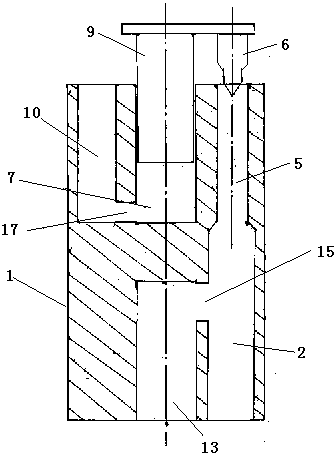
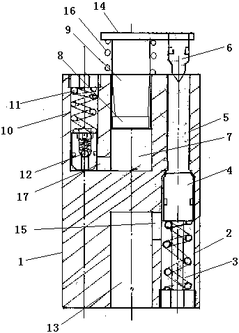
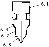
[0023] Refer to attached figure 1 and 2 , a continuous reversing device for layered oil recovery unidirectional pipe string mentioned in the present invention, its technical solution is: comprising a body 1, a starting chamber 2, a pressure relief valve 4, a pressing chamber 5, a starting valve 6, a closing chamber 7, Close the plunger 9, the balance chamber 10, the balance valve 12, the pressure relief chamber 13 and the fixed plate 14, a start chamber 2 is provided at the lower part of one side of the body 1, a pressure relief valve 4 is provided in the start chamber 2, and a pressure relief valve 4 is provided in the pressure relief chamber. The first spring 3 i...


PUM


Abstract

The invention relates to a continuous reversing device and method for a unidirectional pipe string for layered oil recovery. The technical solution is: the fixed plate is moved downward by the liquid pressure of the pipe string from above, and the pressure chamber is closed by starting the valve. At the same time, the balance valve in the balance chamber moves upward to realize energy storage; when the liquid pressure of the pipe string is released, The reverse movement of the balance valve drives the closing plunger to move upwards, which in turn drives the starting valve to move upwards, and opens the pressure chamber, and the pressure relief valve moves down at this time, the communication between the pressure relief chamber and the starting chamber is opened, and the liquid in the pipe string is connected through the lower chamber. The hole enters the pipe string below the body. After the liquid is released, the pressure relief valve moves up, and the lower communication hole is closed by the pressure relief valve. The pipe string above the fixed plate can be pressed by the liquid again, and the above steps are repeated to realize continuous reversing. The beneficial effect is that: the invention can complete the construction of layered oil production with multiple continuous direction reversals in one trip, which greatly saves the process, reduces the labor intensity and operation cost, and shortens the construction period.

Description

technical field [0001] The invention relates to a downhole control device for petroleum, in particular to a continuous reversing device for one-way pipe strings in layered oil recovery. Background technique [0002] In oil field production, multi-level is a common phenomenon. In many layers, the oil-water content of liquid is different. In order to improve efficiency, in oil field production, it is necessary to inject ash, water shut-off agent, chemical water shut-off Block the water layer and exploit the oil layer in order to increase the oil recovery rate, reduce the cost, and increase the benefit. For multi-layer oil production, use the bridge plug to block the non-target oil layer in advance, and then use this new technology string to exploit any target layer. , which can seal the unneeded production reservoirs and realize the oil recovery of the target layer of the oil well. At present, the patent number is 2013104715687, and the patent name is "A Layered Oil Production...

Claims


Application Information

Patent Timeline
Patent Type & Authority Applications(China)
IPC IPC(8): E21B43/14E21B34/14
Inventor 刘玉友
Owner 刘玉友
Learn More