Long-life centrifugal pump cover

A centrifugal pump, long-life technology, applied to pumps, pump components, non-variable pumps, etc., can solve the problems of reduced service life and stability, friction between particles and mechanical seals, mechanical seal damage, etc., to improve service life , enhance temperature resistance, and improve the effect of trial life

Active Publication Date: 2018-01-09
ANHUI WOLONG PUMP & VALVE CO LTD
View PDF6 Cites 8 Cited by
  • Summary
  • Abstract
  • Description
  • Claims
  • Application Information

AI Technical Summary

Problems solved by technology

The mechanical seal cavity 7 of the pump cover 3 of the above-mentioned centrifugal pump is cylindrical and has a small space. If the medium contains particulate matter during use, it is easy to cause friction between the particulate matter and the mechanical seal, causing damage to t

Method used


Image

  • Long-life centrifugal pump cover
  • Long-life centrifugal pump cover
  • Long-life centrifugal pump cover

Examples


Embodiment 1

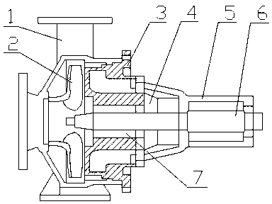
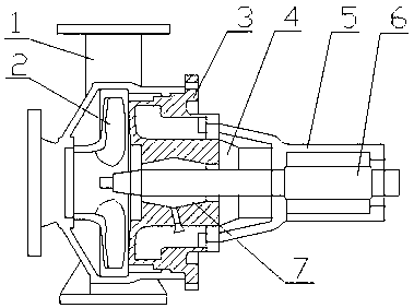
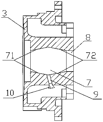
[0021] A pump cover of a long-life centrifugal pump, including a central through hole 8 provided on the pump cover body 3, and the side of the central through hole 8 facing the pump body 1 of the centrifugal pump is provided with a The mechanical seal cavity 7 is characterized in that the inner wall of the mechanical seal cavity 7 is divided into a left inner wall 71 and a right inner wall 72, and the cross-sectional shape of the mechanical seal cavity 7 composed of the left inner wall 71 and the right inner wall 72 is spinning. Conical, the intersection of the bottom of the left inner wall 71 and the right inner wall 72 is provided with a through-hole 9 that passes through the pump cover body 3, and the bottom of the through-hole 9 is provided with a sealing plug 10. Both the left inner wall 71 and the right inner wall 72 are coated with anti-corrosion and wear-resistant paint.

[0022] Further, the left inner wall 71 and the right inner wall 72 incline at the same angle, and...

Embodiment 2

[0030] A pump cover of a long-life centrifugal pump, including a central through hole 8 provided on the pump cover body 3, and the side of the central through hole 8 facing the pump body 1 of the centrifugal pump is provided with a The mechanical seal cavity 7 is characterized in that the inner wall of the mechanical seal cavity 7 is divided into a left inner wall 71 and a right inner wall 72, and the cross-sectional shape of the mechanical seal cavity 7 composed of the left inner wall 71 and the right inner wall 72 is spinning. Conical, the intersection of the bottom of the left inner wall 71 and the right inner wall 72 is provided with a through-hole 9 that passes through the pump cover body 3, and the bottom of the through-hole 9 is provided with a sealing plug 10. Both the left inner wall 71 and the right inner wall 72 are coated with anti-corrosion and wear-resistant paint.

[0031] Further, the left inner wall 71 and the right inner wall 72 incline at the same angle, and...


PUM


Abstract

The invention discloses a long-life centrifugal pump cover. The long-life centrifugal pump cover comprises a center through hole formed in a pump cover body. A mechanical seal cavity connected with the center through hole is formed in one side, towards a centrifugal pump body, of the center through hole. The long-life centrifugal pump cover is characterized in that the inner wall of the mechanicalseal cavity is divided into the left side inner wall and the right side inner wall, the cross section of the mechanical seal cavity formed by the left side inner wall and the right side inner wall isin a spinning cone shape, an impurity-removing through hole penetrating out of the pump cover body is formed in the intersection of the bottoms of the left side inner wall and the right side inner wall, a sealing plug is arranged at the bottom end of the impurity-removing through hole, and the left side inner wall and the right side inner wall are both coated with anti-corrosion and wear-resistant coating. According to the long-life centrifugal pump cover, special optimizing treatment is conducted on the structure of the centrifugal pump cover and the treatment technology, so that the use qualities of the operating stability, the wear resistance, the corrosion prevention and the like of the long-life centrifugal pump cover are effectively promoted, the service life is obviously prolongedby about 35%, and the comprehensive using and promoting value is high.

Description

technical field [0001] The invention belongs to the technical field of centrifugal pump processing and manufacturing, and in particular relates to a pump cover of a long-life centrifugal pump. Background technique [0002] Centrifugal pump refers to the pump that transports liquid by the centrifugal force generated when the impeller rotates. It can transport more media. It is a common power machine in modern people's daily life and industrial production. The existing common horizontal single-stage centrifugal pumps have many structures such as figure 1 As shown, it includes pump body 1, impeller 2, pump cover 3, mechanical seal gland 4, suspension 5 and shaft 6, pump cover 3 is fixed on one side of pump body 1, and a gap is formed between pump cover 3 and pump body 1. Install the pump chamber of the impeller 2, the suspension 5 is fixed on one side of the pump cover 3, the shaft 6 is supported in the suspension 5 through a bearing and one end of the shaft 6 extends into the...

Claims


Application Information

Patent Timeline
IPC IPC(8): F04D29/42C09D4/02C09D4/06C09D7/61C09D7/63C09D5/08
Inventor 洪忠保程志强
Owner ANHUI WOLONG PUMP & VALVE CO LTD
Why Eureka
Try Eureka