Air-leaking-reducing anti-ash-blocking system and method for rotary air preheater

An air preheater, rotary technology, applied in the direction of combustion method, air induction, lighting and heating equipment, etc., can solve problems such as blockage and large air leakage, increased fan power consumption, increased operating costs, etc., to reduce low temperature Corrosion and dust accumulation, avoiding the increase of fan power consumption, and reducing the effect of carrying air leakage

Pending Publication Date: 2018-01-09
孙孝禹 +1
View PDF0 Cites 6 Cited by
  • Summary
  • Abstract
  • Description
  • Claims
  • Application Information

AI Technical Summary

Problems solved by technology

[0002] The rotary air preheater is a heat exchange device that uses the heat of flue gas at the tail of the boiler to heat the air required for combustion. It is widely used in thermal power units at present, but its low-temperature corrosion, blockage and large air leakage have always plagued the project. Technical staff
[0003] The disadvantage of the above method is that once the heater is damaged, it can only be replaced when the unit is out of service for a long time or when it is overhauled, which increases the risk of equipment operation; and the hot air recirculation device sends the hot air drawn from the outlet of the air preheater to Returning to the inlet of the blower, the hot air is mixed with cold air and then flows through the air preheater, which will increase the air volume at the fan inlet, thereby increasing the power consumption of the fan, and with the increase of the recirculation of hot air, the fan’s Power consumption increases sharply, greatly increasing operating costs

Method used


Image

  • Air-leaking-reducing anti-ash-blocking system and method for rotary air preheater
  • Air-leaking-reducing anti-ash-blocking system and method for rotary air preheater
  • Air-leaking-reducing anti-ash-blocking system and method for rotary air preheater

Examples


Embodiment 1

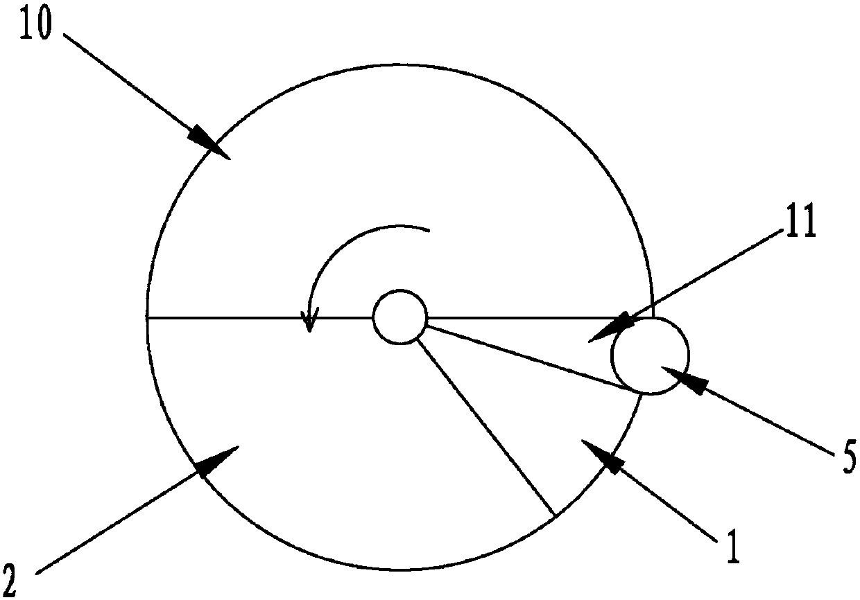
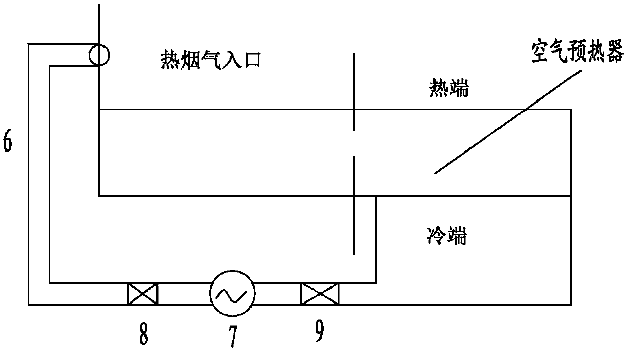
[0020] Such as figure 1 , image 3 As shown, Embodiment 1 of the air leakage and anti-clogging system of the rotary air preheater of the present invention, wherein the rotary air preheater is internally provided with a flue gas bin 10, a primary air bin 1, and a secondary air bin 2 , Heat storage element. Embodiment 1 of the air leakage and anti-blocking ash system of the rotary air preheater of the present invention, wherein the flue gas bin 10, the secondary air bin 2, and the primary air bin 1 are along the direction of the arrow (i.e. figure 1 Arranged in the counterclockwise direction), the heat storage element is arranged in the direction of the arrow (ie figure 1 (shown counterclockwise), that is, the heat storage element passes through the flue gas bin 10, the secondary air bin 2, and the primary air bin 1 in sequence.

[0021] The air leakage and anti-blocking ash system of the rotary air preheater includes a flue gas recirculation sub-bin 11 and a flue gas recircu...

Embodiment 2

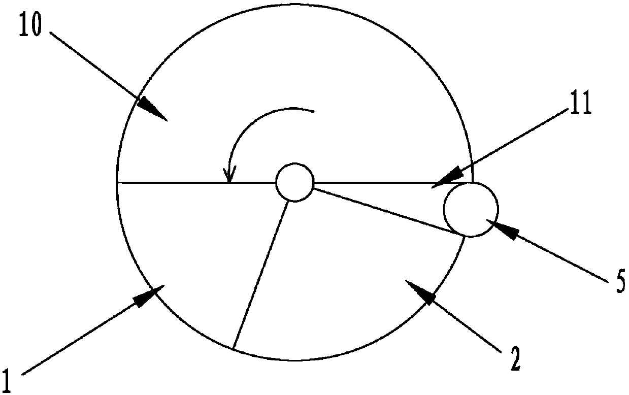
[0026] Such as figure 2 As shown, Embodiment 2 of the air leakage and anti-blocking ash system of the rotary air preheater of the present invention, wherein the rotary air preheater is equipped with a flue gas bin 10, a primary air bin 1, and a secondary air bin 2 , Heat storage element. Embodiment 2 of the air leakage and anti-blocking ash system of the rotary air preheater of the present invention, wherein the flue gas bin 10, the primary air bin 1, and the secondary air bin 2 are arranged along the direction of the arrow (i.e. figure 1 Arranged in the counterclockwise direction), the heat storage element is arranged in the direction of the arrow (ie figure 1 (shown counterclockwise), that is, the heat storage element passes through the flue gas bin 10, the primary air bin 1, and the secondary air bin 2 in sequence. The air leakage and anti-blocking ash system of the rotary air preheater includes a flue gas recirculation sub-bin 11 and a flue gas recirculation system 5. O...


PUM


Abstract

The invention relates to an air-leaking-reducing anti-ash-blocking system and a method for a rotary air preheater. The air-leaking-reducing anti-ash-blocking system comprises a flue gas recirculationbranch warehouse, wherein one side of the flue gas recirculation branch cabin is adjacent to a flue gas cabin; the other side of the flue gas recirculation branch cabin is adjacent to a primary air cabin or a secondary air cabin; and flue gas in the flue gas recirculation branch cabin is used for heating a heat storage element, which is rotated out from the primary air cabin or the secondary air cabin and is rotated into the flue gas cabin. The method provided by the invention comprises the step of utilizing the flue gas in a flue gas inlet air channel of the rotary air preheater for heating the heat storage element, which is rotated out from the primary air cabin or the secondary air cabin and is rotated into the flue gas cabin. The technical scheme provided by the invention can replace an air heater and a hot air recirculation device, and is simpler and more practical compared with the air heater and the hot air recirculation device at the same time, and the air preheater has betteranti-corrosion and anti-blocking effects; and meanwhile, the carrying air leakage and one-side air leakage of the air preheater are reduced, so that an air leakage coefficient of the air preheater isgreatly reduced.

Description

technical field [0001] The invention relates to the technical field of heating, in particular to a system and method for reducing air leakage and preventing dust blocking of a rotary air preheater. Background technique [0002] The rotary air preheater is a heat exchange device that uses the heat of flue gas at the tail of the boiler to heat the air required for combustion. It is widely used in thermal power units at present, but its low-temperature corrosion, blockage and large air leakage have always plagued the project. Technical staff. At present, the main method to prevent low-temperature corrosion and blockage of the air preheater is to increase the inlet cold air temperature of the air preheater through hot air recirculation and heaters, thereby increasing the temperature of the metal components at the cold end of the air preheater to make the temperature as high as possible The ground is higher than the acid dew point of the flue gas, reducing the corrosion and clog...

Claims


Application Information

Patent Timeline
Patent Type & Authority Applications(China)
IPC IPC(8): F23L15/02F23L17/04
CPCY02E20/34
Inventor 孙孝禹解海龙
Owner 孙孝禹
Why Eureka
Try Eureka