Detection device for detecting stress of pantograph on overhead line system

A detection device and catenary technology, which is applied in the field of image recognition, can solve problems such as large structure, large catenary lift, pantograph-catenary accidents, etc., and achieve the effect of simple system structure, convenient installation and maintainability

Active Publication Date: 2018-01-09
NANJING TYCHO INFORMATION TECH
View PDF16 Cites 3 Cited by
  • Summary
  • Abstract
  • Description
  • Claims
  • Application Information

AI Technical Summary

Problems solved by technology

[0003] In the high-speed electrified railway system, it is necessary to maintain a stable current receiving state, requiring a certain contact pressure between the pantograph and the catenary. When the contact pressure is too small, it has been offline, that is, the pantograph is separated from the contact line and an arc is generated; When the contact pressure is too large, the lift of the contact wire is too large, causing the contact wire to bend locally, causing fatigue damage to the contact wire, and at the same time increasing the wear of the contact wire, causing pantograph-catenary accidents in severe cases
[0004] Patent No.: 200720082607.4 An online dynamic detection device for locomotive pantograph contact pressure. The device adopts the mechanical method of pressure sensor, has a large structure, is extremely heavy, and is inconvenient to install and maintain. Therefore, it is necessary to develop a suitable pantograph to catenary Stress detection method and device

Method used


Image

  • Detection device for detecting stress of pantograph on overhead line system
  • Detection device for detecting stress of pantograph on overhead line system
  • Detection device for detecting stress of pantograph on overhead line system

Examples


Embodiment approach

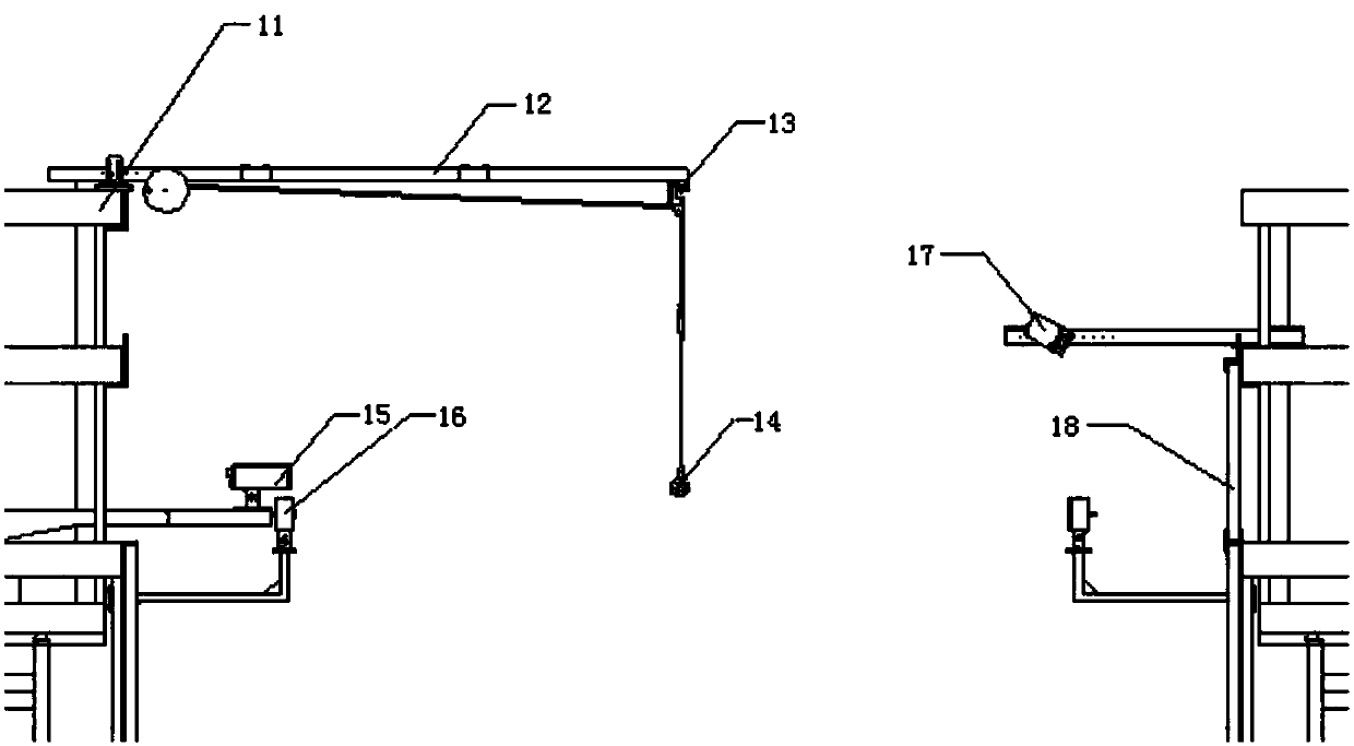
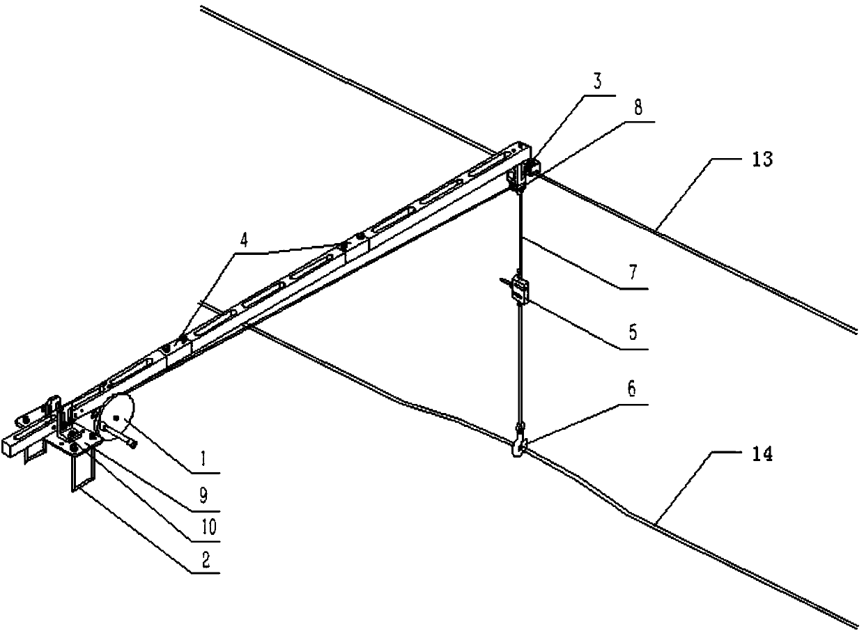
[0033] The detection device of the pantograph to the catenary stress of the present embodiment, the system includes a camera, a white background board, a background board flashlight, a trigger sensor, and a tension detection device. The camera and the white background board are installed on the same horizontal plane as the catenary, and the trigger sensor is installed on About 100mm directly below the camera, see Figure II Connect the three support frames with the insulating adapter 4, fix the wire clamp 3 on the top of the right support frame, the wire clamp 3 contains bearings and pulleys, and the pulley part is made of nylon material; fix a set of fixed pulleys 8 on the top of the right support frame ;The winding device 1 is installed on the left support frame, and the winding device 1 contains a brake fastening bolt, which is used to brake the rope 7 in time to ensure the accuracy of the pulling force when the camera is shooting; the hook 6, the pressure sensor 5 , the ro...


PUM


Abstract

The invention discloses a detection device for detecting the stress of a pantograph on an overhead line system. The detection device comprises a camera, a white background board, a background board flash lamp, a trigger sensor and a pull force detection device; and the camera and the background board are installed on the same horizontal plane with the overhead line system; and the trigger sensor is installed below the camera. When pulling upwards the overhead line system, the pull force detection device is in linkage with the camera, so that photographing can be performed, and therefore, a displacement and pull force corresponding diagram can be obtained; the pull force detection device is removed, only the camera, the background board, the background board flash lamp and the trigger sensor are left on a site. During detection, when a pantograph at the top of a train passes the trigger sensor, the camera shoots a set of photos of the raised state of the overhead line system during thecontact of the overhead line system with the pantograph; and an actual pull force value is obtained through the comparison of the pixel value of the photos with the displacement and pull force corresponding diagram. The detection device of the method is simple and quick, does not occupy a space, has high safety and high reliability, and can better serve pantograph-overhead line system safe contactin the railway industry.

Description

technical field [0001] The invention relates to the field of image recognition, more precisely, to a method and device for detecting the stress of a pantograph on a catenary in rail transit. Background technique [0002] Catenary is a special form of transmission line erected along the railway line to supply power to electric locomotives. The catenary is responsible for the important task of directly transmitting the electric energy obtained from the traction substation to the electric locomotive. Therefore, the quality and working status of the catenary directly affect the transportation capacity of the electrified railway. [0003] In the high-speed electrified railway system, it is necessary to maintain a stable current receiving state, requiring a certain contact pressure between the pantograph and the catenary. When the contact pressure is too small, it has been offline, that is, the pantograph is separated from the contact line and an arc is generated; When the conta...

Claims


Application Information

Patent Timeline
IPC IPC(8): G01L1/24G01L5/04
Inventor 石峥映梅劲松郭其昌蒋银男袁泉
Owner NANJING TYCHO INFORMATION TECH
Why Eureka
Try Eureka