Clamp for bursting test of geosynthetic material and using method thereof

A geosynthetic material and testing technology, applied in analytical materials, measuring devices, instruments, etc., can solve the problems of high production cost, slippage of samples, poor controllability of pneumatic devices, etc., and achieve convenient operation, convenient loading and unloading, and controllable high sex effect

Pending Publication Date: 2018-01-09
TIANJIN PORT ENG INST LTD OF CCCC FIRST HARBOR ENG +2
View PDF9 Cites 7 Cited by
  • Summary
  • Abstract
  • Description
  • Claims
  • Application Information

AI Technical Summary

Problems solved by technology

[0003] When carrying out the burst test, the working principle of the traditional fixture is to connect a piece of annular fixture with the fixture of the fixed base, and manually tighten the bolts to clamp the two pieces of fixture, so as to fix the sample between the fixtures. However, this method operates It is cumbersome, time-consuming and labor-intensive, and it is very easy to have the defect that the sample slips due to insufficient clamping force
At present, there are some structurally improved bursting fixtures on the market. The principle is mostly to use cylinder drive instead of manual clamping to clamp the fixture. Although this method is easy to operate, the overall structure of the cylinder drive device is relatively cumbersome, the production cost is high, and the air pipe joint is relatively expensive. There are too many, which makes the connection operation more complicated. In addition, the controllability of the pneumatic device is poor, it is difficult to control the clamping force of the fixture, and it is easy to cause the fixture to deform

Method used


Image

  • Clamp for bursting test of geosynthetic material and using method thereof

Examples


Embodiment Construction

[0022] The technical solutions of the present invention will be further described below in conjunction with specific embodiments.

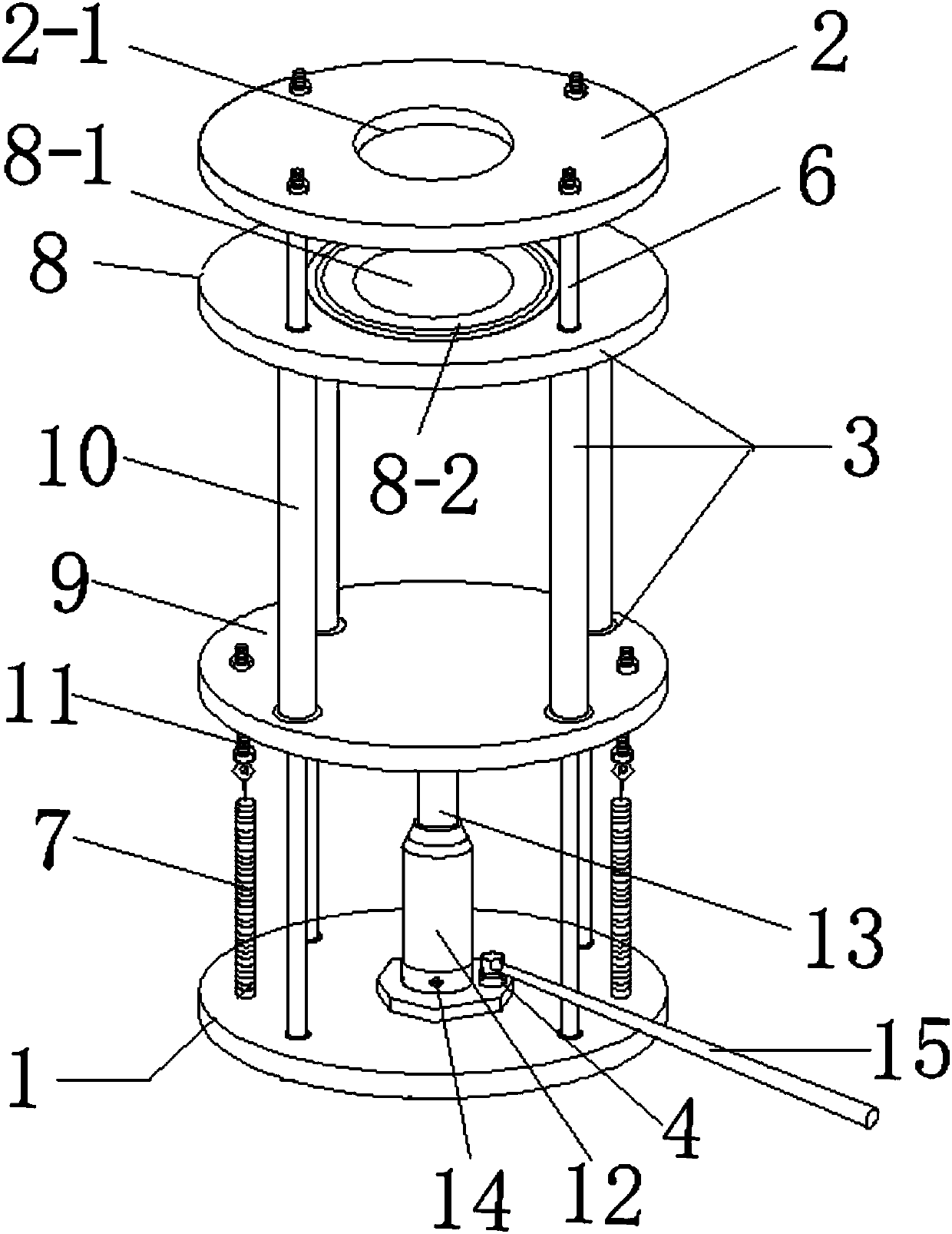
[0023] Such as figure 1 As shown, a geosynthetic material bursting test fixture includes a base 1, an upper splint 2, a movable lower splint 3 and a hydraulic jack 4,

[0024] The base 1 is disc-shaped, and four slide bars 6 are vertically arranged on the base 1, and two extension springs 7 are also arranged on the base 1;

[0025] The movable lower splint 3 is composed of a lower splint 8, a chassis 9, four hollow connecting rods 10, and hook bolts 11. The lower splint 8 and the chassis 9 are connected by the hollow connecting rods 10, and the positions of the four hollow connecting rods 10 are aligned with the four sliding The positions of the rods 6 are corresponding, and the inner diameter of the hollow connecting rod 10 is slightly larger than the diameter of the sliding rod 6, so that the four hollow connecting rods 10 can be slidably inser...


PUM


Abstract

The invention discloses a clamp for a bursting test of a geosynthetic material. The clamp comprises a base, an upper clamping plate, a movable lower clamping plate and an oil jack, wherein the base isvertically provided with multiple sliding rods; the movable lower clamping plate is formed by a lower clamping plate, a chassis and hollow connecting rods; the lower clamping plate and the chassis are connected through the hollow connecting rods; the hollow connecting rods of the movable lower clamping plate sleeve the sliding rods; the upper clamping plate is fixed to the top ends of the slidingrods; the oil jack is arranged in the axis of the base, and the chassis is enabled to be in contact with the top end of a piston rod of the oil jack. During use, a cylindrical geosynthetic material testing sample can be put on the lower clamping plate, then a rocking rod of the oil jack can be shaken, and the piston rod is enabled to ascend to erect the movable lower clamping plate until the geosynthetic material testing sample is clamped by the lower clamping plate and the upper clamping plate. According to the clamp disclosed by the invention, the operation is convenient, ascending and descending of the piston rod of the oil jack can be freely controlled by utilizing the manual rocking rod, so that the magnitude of a clamping force can be effectively controlled, and the controllabilityis higher.

Description

technical field [0001] The invention belongs to the technical field of fixtures for geotechnical tests, and in particular relates to a fixture for burst tests of geosynthetics and a use method thereof. Background technique [0002] Burst test of geosynthetics is an important method to measure its mechanical properties. The test principle is to clamp the sample in the fixture of the fixed base, and the testing machine drives the ejector rod to move down vertically at a certain speed. At this time, the force sensor of the testing machine starts to transmit the data to the computer acquisition system until the sample is broken, so as to obtain its maximum breaking strength. [0003] When carrying out the burst test, the working principle of the traditional fixture is to connect a piece of ring fixture with the fixture of the fixed base, and manually tighten the bolts to clamp the two pieces of fixture, so as to fix the sample between the fixtures. However, this method operates ...

Claims


Application Information

Patent Timeline
Patent Type & Authority Applications(China)
IPC IPC(8): G01N3/04
Inventor 朱耀庭马桂林袁方龙高贝贝田伟刘和文李明英郑爱荣陈举曹芳
Owner TIANJIN PORT ENG INST LTD OF CCCC FIRST HARBOR ENG
Why Eureka
Try Eureka