
Relocation method and device of terminal location, terminal and storage medium

A terminal position and relocation technology, applied in the field of relocation, can solve the problems of increasing labor costs, increasing use costs, reducing robot autonomy, etc., to achieve the effect of reducing excessive consumption and ensuring accuracy

Active Publication Date: 2018-01-09
GUANGZHOU SHIYUAN ELECTRONICS CO LTD
View PDF5 Cites 12 Cited by
  • Summary
  • Abstract
  • Description
  • Claims
  • Application Information

AI Technical Summary

Problems solved by technology

[0004] However, the method of using multiple sensors for relocation not only increases the cost of use, but also is not suitable for indoor environments (such as GPS, etc.), or requires the deployment of sensors in the environment (such as ZigBee and other wireless positioning solutions), which increases the difficulty of use
At the same time, only using the artificially designated relocation area for relocation will increase labor costs and reduce the autonomy of the robot; relocating the entire known map environment as a relocation area will increase the randomness of relocation and consume a lot of calculations resources and time; while using artificial feature matching to find the relocation area can reduce the randomness of relocation and reduce calculation time, but because the artificial feature points extracted from the lidar data require preset extraction rules, usually only line segments can be extracted , corners, arcs and other features are limited by manually determined data features, and can only be applied to simple and regular indoor environments

Method used


Image

  • Relocation method and device of terminal location, terminal and storage medium
  • Relocation method and device of terminal location, terminal and storage medium
  • Relocation method and device of terminal location, terminal and storage medium

Examples


Embodiment 1

[0038] Figure 1a It is a schematic flowchart of a method for relocating a terminal location provided by Embodiment 1 of the present invention. This method is suitable for relocating the location of the terminal when the initialization or positioning of the terminal location fails. implemented by a device, where the device may be implemented by software and / or hardware, and generally integrated into a control device of a terminal.

[0039] It should be noted that the terminal may specifically refer to electronic terminal devices capable of performing related tasks by themselves, such as robots, smart furniture devices, and smart service devices. It can be understood that when the above-mentioned terminal performs position initialization or when the position information is wrong during the working process, the position of the terminal needs to be relocated. Based on the method for relocating the terminal position provided in this embodiment, the terminal position can be quickly ...

Embodiment 2

[0057] Figure 2a It is a schematic flowchart of a method for relocating a terminal location provided by Embodiment 2 of the present invention. Embodiment 2 of the present invention is optimized based on the above embodiment. In this embodiment, further optimization is added: construction and training learning center LiDAR classifier described above.

[0058] On the basis of the above optimization, further optimize the construction and training of the laser radar classifier as follows: after the trained data feature network model, the classification network model to be trained is added to form a laser radar classifier to be trained; At least one frame of historical radar data is input into the data feature network model to obtain the data feature vector of the at least one frame of historical radar data; according to the data feature vector of each historical radar data and the classification division strategy set, determine each historical radar A standard classification lab...

Embodiment 3

[0111] image 3 It is a schematic flowchart of a method for relocating a terminal location provided by Embodiment 3 of the present invention. The embodiment of the present invention is optimized based on the above embodiments. In this embodiment, it is further determined that the terminal is relocated in the global map at the current moment based on the initial candidate location set and the set relocation strategy. The target position of the target position is embodied as: using multivariate Gaussian distribution sampling to determine the prior probability distribution of each candidate position in the initial candidate position set at the current moment of the terminal; in the posterior probability distribution determined according to the prior probability distribution , determining that the candidate position corresponding to the maximum a posteriori probability value is the target position for relocation of the terminal in the global map at the current moment.

[0112] At...


PUM


Abstract

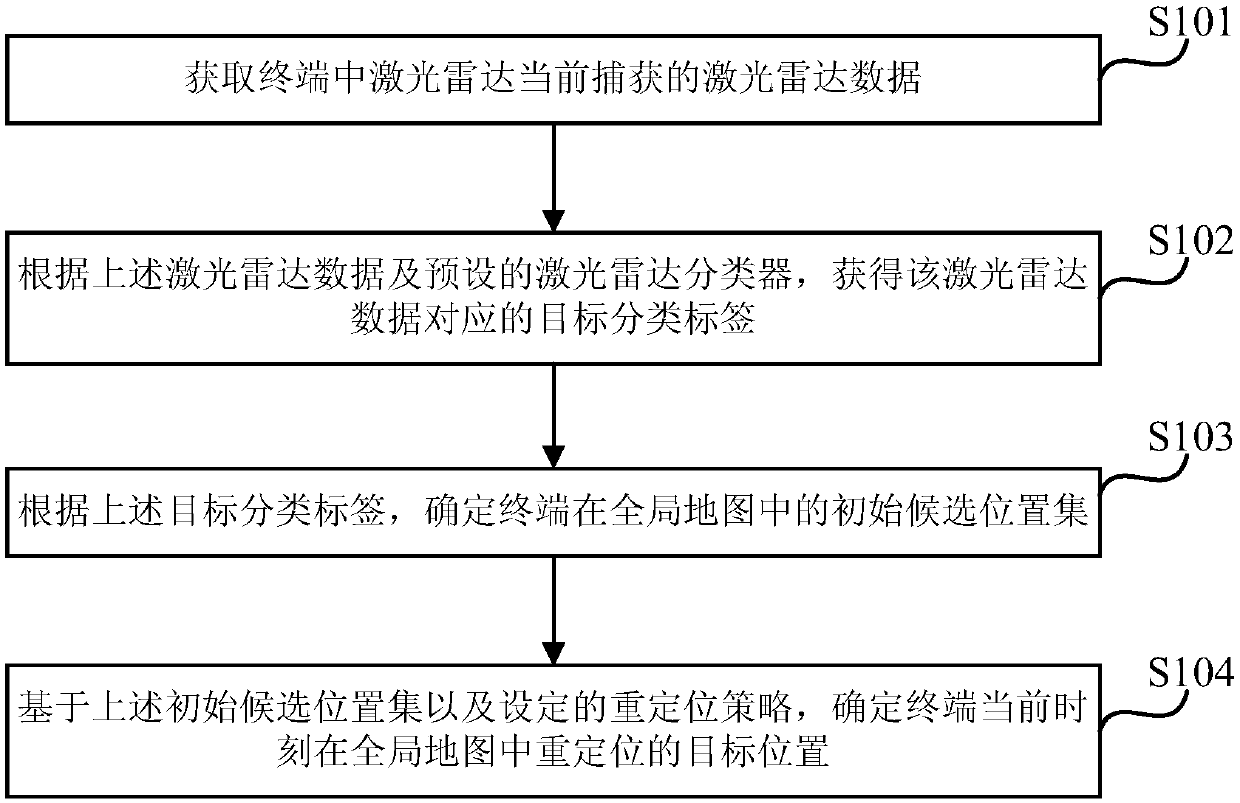
The invention discloses a relocation method and device of a terminal location, a terminal and a storage medium. The method comprises: laser radar data currently captured by a laser data in a terminalare obtained; according to the laser radar data and a preset laser radar classifier, a target classification tag corresponding to the laser radar data is obtained; according to the target classification tag, an initial candidate position set of the terminal in a global map is determined; and on the basis of the initial candidate position set and a set relocation strategy, a re-localized target position of the terminal in the global map at a current time is determined. With the method disclosed by the invention, effective selection of the relocation candidate area is realized, so that the highaccuracy of the relocation result during relocation of the terminal in the relocation candidate area is guaranteed; excessive consumption of computing resources and time is reduced and the limitationcaused by manual determination of a feature point is avoided. The relocation method and device can be applied to a complicated external environment.

Description

technical field [0001] The present invention relates to the technical field of relocation, in particular to a method, a device, a terminal and a storage medium for relocating a terminal location. Background technique [0002] When the robot is initialized for the first time in a known map, or after the robot has been running for a long time, when the robot positioning fails due to sensor data errors, less environmental information, and cumulative errors, etc., in order to ensure the normal positioning of the robot, it is necessary to Do the relocation. [0003] The existing robot relocation methods are generally divided into two types: one is to use multiple sensors to obtain more environmental information, first perform rough positioning to find the relocation area, and then use the positioning algorithm to perform positioning, and gradually converge to obtain the correct positioning result; Another method is to use only lidar data for relocation. The simpler method in thi...

Claims


Application Information

Patent Timeline
IPC IPC(8): G01S17/08G06K9/62
Inventor 阳方平曹军曾碧
Owner GUANGZHOU SHIYUAN ELECTRONICS CO LTD
Learn More