
Finite element modeling method of welding nut based on automobile fatigue simulation

A welding nut and finite element technology, applied in design optimization/simulation, geometric CAD, etc., can solve problems such as inaccurate stress analysis and achieve an effect that is easy to master

Active Publication Date: 2020-05-01
SAIC VOLKSWAGEN AUTOMOTIVE CO LTD
View PDF2 Cites 0 Cited by
  • Summary
  • Abstract
  • Description
  • Claims
  • Application Information

AI Technical Summary

Problems solved by technology

For automobile fatigue simulation, it is often necessary to analyze the area with large local stress. However, the traditional modeling method can only do more accurate analysis of the stress outside the bolt connection area because it ignores the actual force mechanism of the connection. The stress analysis of the connection itself will be very inaccurate. In addition, a large number of experiments have proved that the connection area of ​​the weld nut happens to be a common place where cracks occur. Therefore, the finite element modeling method for the weld nut in the prior art has a significant effect. defect

Method used


Image

  • Finite element modeling method of welding nut based on automobile fatigue simulation
  • Finite element modeling method of welding nut based on automobile fatigue simulation
  • Finite element modeling method of welding nut based on automobile fatigue simulation

Examples


Embodiment Construction

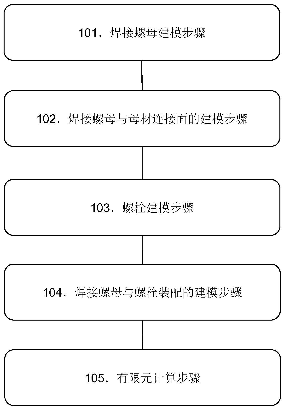
[0034] refer to figure 1 as shown, figure 1 Disclosed is a flow chart of a finite element modeling method for welding nuts based on automobile fatigue simulation according to an embodiment of the present invention. The finite element modeling method for welding nuts of the present invention will be described below in conjunction with a specific example.

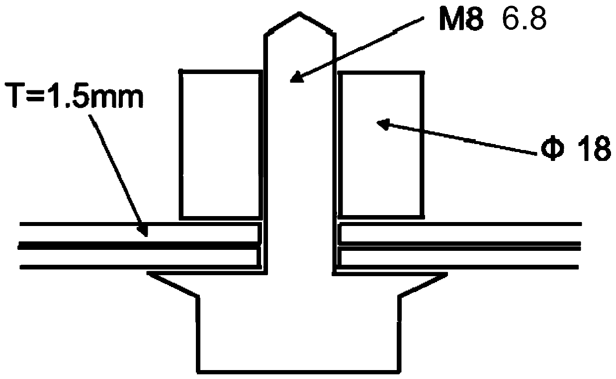
[0035] This example simulates the cracking of a tail pipe bracket with welded nuts in a fatigue test of a development vehicle. The diameter of the welding nut is 18mm, the bolt is M8, grade 6.8, and there are three equal welding lines at the edge, such as figure 2 as shown, figure 2 A schematic structural view of the weld nut of this example is disclosed. The weight of the exhaust pipe and muffler is 13.5 kg, the thickness of the tail pipe bracket is 1.5mm, the material is H260, and the yield limit is 272MPa. In this example, the connection structure of welding nuts, bolts and base metal is as follows: image 3 as show...


PUM


Abstract

The invention discloses a welding nut finite element modeling method based on automobile fatigue simulation. The method includes the following steps that welding nut modeling is conducted, wherein a solid element network of a welding nut and a base metal is established through point adding and projection; modeling of a welding-nut and base-metal connection surface is conducted, wherein contact modeling is conducted on a bonding wire, the welding nut and the base metal; modeling of a bolt is conducted, wherein the bolt matched with the welding nut is subjected to modeling; modeling of assemblyof the welding nut and the bolt is conducted, wherein modeling of connection of the bolt and the welding nut is conducted, and pretightening force of the bolt is set; finite element calculation is conducted, the established model is moved into a fatigue finite element calculation model, and through the simulation of a finite element program, the force bearing mode of the finite element welding nutis obtained. The method not only considers the connection structure of a welding place, but also considers the contact effect of the nut to a plate, the deformation behavior of the welding nut in thefatigue simulation can be accurately simulated, and accurate plate stress distribution is obtained.

Description

technical field [0001] The invention relates to the field of automobile manufacturing, more specifically, to a simulation test method in the automobile manufacturing process. Background technique [0002] A weld nut is a nut that is suitable for welding on the outer edge of the nut. It is generally made of weldable materials and is relatively thick and suitable for welding. Welding is equivalent to turning two separate parts into a whole. The metals are melted at high temperature, mixed together and then cooled, and alloys are added in the middle. The interior of the weld nut is generally stronger than the nut under the action of molecular force. The advantages of welding nuts are high strength, wide range of use, and thickness. However, due to high temperature, the connected parts will be deformed and cannot be disassembled, and some active metals are not suitable for welding by this method, such as aluminum, magnesium, etc., and shielding gas is required. Fire argon arc ...

Claims


Application Information

Patent Timeline
Patent Type & Authority Patents(China)
IPC IPC(8): G06F30/15G06F30/23
Inventor 李天兵连志斌杨涵徐成民
Owner SAIC VOLKSWAGEN AUTOMOTIVE CO LTD
Learn More