
Optical receiving module and optical communication device

A technology of an optical receiving module and an optical transmitting module, which is applied in the field of optical signal processing, can solve problems such as edge collapse at the output end of an arrayed waveguide grating, and achieve the goals of avoiding failure, improving reliability and practicability, and improving safety and practicability Effect

Pending Publication Date: 2018-01-09
CHENGDU SUPERXON COMM TECH CO LTD
View PDF5 Cites 6 Cited by
  • Summary
  • Abstract
  • Description
  • Claims
  • Application Information

AI Technical Summary

Problems solved by technology

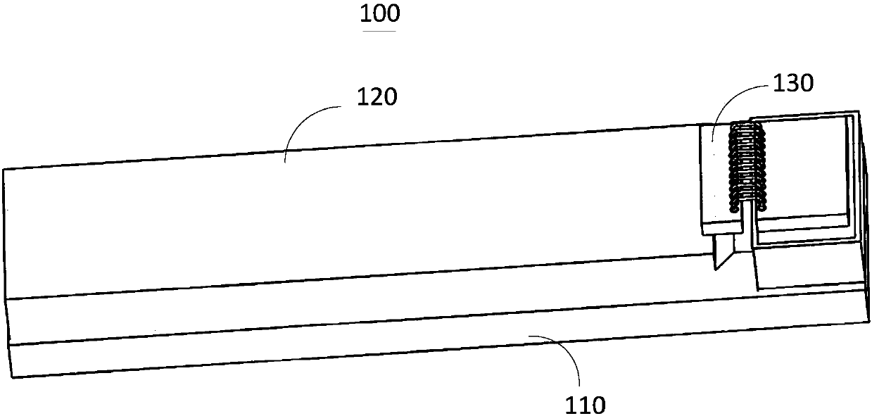
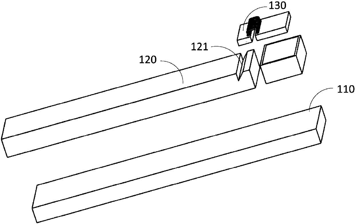
[0004] In view of this, the object of the present invention is to provide a light receiving module and an optical communication device to solve the problems caused by the arrayed waveguide grating in the prior art due to the need to cut the inclined surface at the output end of the arrayed waveguide grating to reflect the optical signal to the photodetector. There is a problem of edge collapse at the output end of the raster

Method used


Image

  • Optical receiving module and optical communication device
  • Optical receiving module and optical communication device
  • Optical receiving module and optical communication device

Examples


Embodiment Construction

[0031] In order to make the purpose, technical solutions and advantages of the embodiments of the present invention clearer, the technical solutions in the embodiments of the present invention will be clearly and completely described below in conjunction with the drawings in the embodiments of the present invention. Obviously, the described embodiments It is only a part of embodiments of the present invention, but not all embodiments. The components of the embodiments of the invention generally described and illustrated in the figures herein may be arranged and designed in a variety of different configurations.

[0032] Accordingly, the following detailed description of the embodiments of the invention provided in the accompanying drawings is not intended to limit the scope of the claimed invention, but merely represents selected embodiments of the invention. Based on the embodiments of the present invention, all other embodiments obtained by persons of ordinary skill in the a...


PUM


Abstract

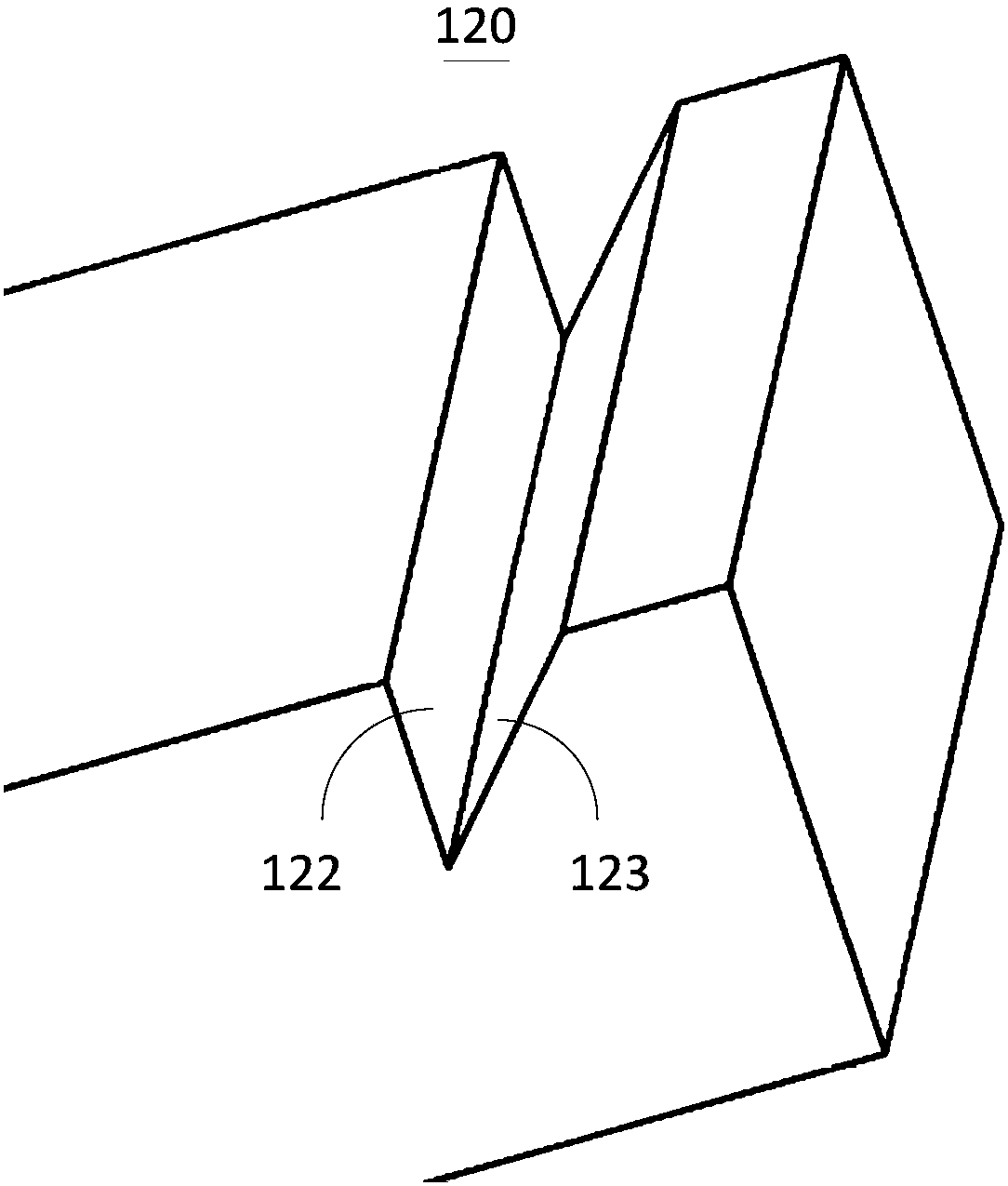
The invention provides an optical receiving module and an optical communication device, and relates to the field of optical signal processing technology. The optical receiving module comprises: a first substrate; an array waveguide grating arranged on the surface of the first substrate, wherein a V-shaped groove is formed in one side of the array waveguide grating away from the first substrate; and a photoelectric detector, wherein the photoelectric detector is arranged on one side of the array waveguide grating away from the first substrate and opposite to the V-shaped groove to reduce lightsignals output from the V-shaped groove and convert the light signals into electric signals. As the V-shaped groove is formed in the array waveguide grating, the problem that an inclined plane needs to be cut on the output end of the array waveguide grating to reflect the light signals to the photoelectric detector, resulting in edge breakage of the output end of the array waveguide grating in related art, is solved.

Description

technical field [0001] The present invention relates to the technical field of optical signal processing, in particular to an optical receiving module and an optical communication device. Background technique [0002] With the deepening of signal diversification, people have higher and higher requirements for the transmission of audio, video and other information. In the field of communication, optical communication is widely used in various industries due to its characteristics of large transmission capacity, high security performance and good anti-interference performance. In the optical receiving module including wavelength division multiplexing technology, according to the different devices for wavelength division multiplexing, it generally includes multilayer thin film technology and arrayed waveguide grating technology. Among them, arrayed waveguide grating technology is widely used due to its advantages of small waveguide size and high-density packaging structure. ...

Claims


Application Information

Patent Timeline
IPC IPC(8): H04B10/60H04B10/66H04B10/67
Inventor 严强杨标连小龙
Owner CHENGDU SUPERXON COMM TECH CO LTD
Learn More