

Automatic pipe expanding machine
A pipe expander and automatic technology, applied in metal processing equipment, feeding devices, manufacturing tools, etc., can solve the problems of low manual operation efficiency, misalignment of pipes, time-consuming and laborious, etc., to achieve simple structure, avoid pipe stuck, Anti-shake effect
- Summary
- Abstract
- Description
- Claims
- Application Information
AI Technical Summary
Problems solved by technology
Method used
Image

Examples
Embodiment 1
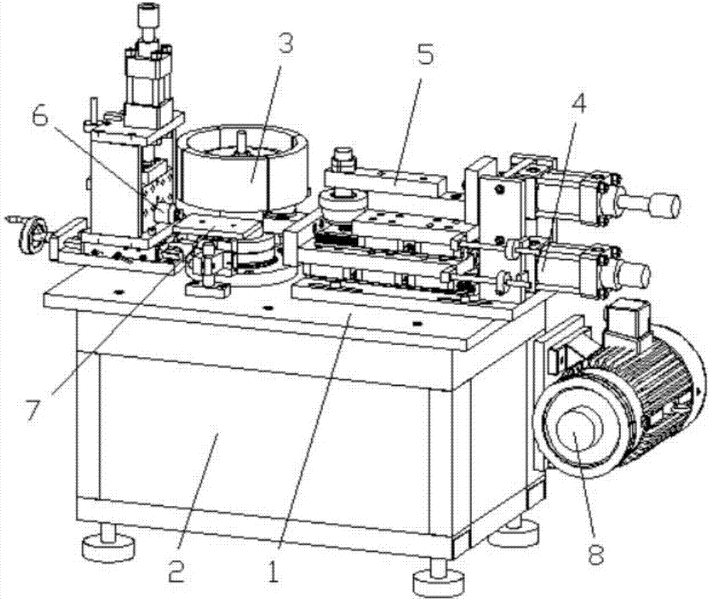
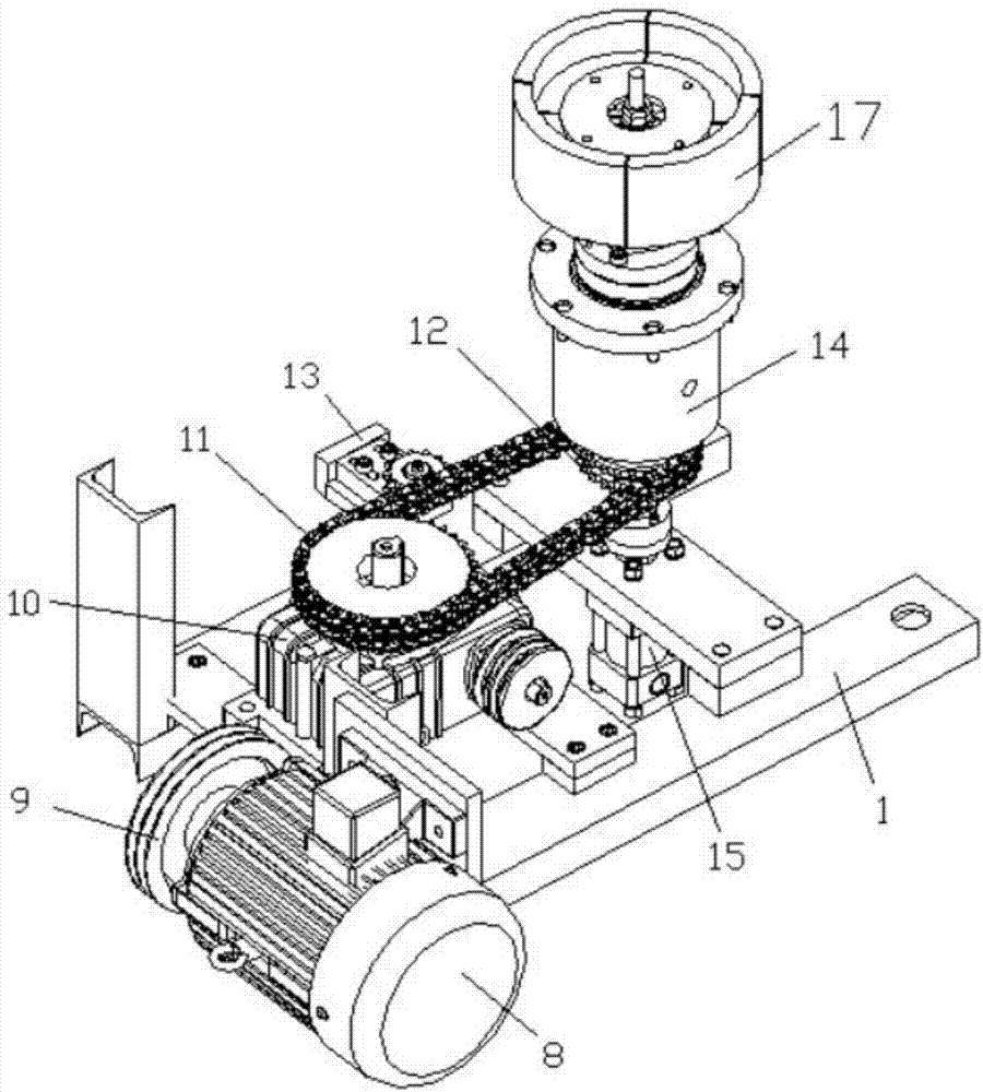
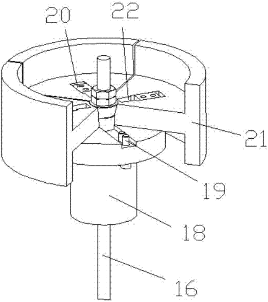
[0034] Such as Figure 1-Figure 8As shown, the specific structure of the present invention is: an automatic tube expanding machine, which includes a frame 1 and a power distribution control box 2, the frame 1 is provided with a tube expanding material loading device 3, and the described tube expanding The loading device 3 includes a loading tube expander 17 matched with the pipe, the bottom of the loading tube expander 17 is connected with a loading rotating shaft 16, and the loading rotating shaft 16 is connected with a sprocket 12 and a chain 11. The output shaft of the power commutator 10, the input shaft of the power commutator 10 is connected to the pipe expansion rotating motor 8 through the transmission wheel 9 and the transmission belt, and the described material-carrying pipe expander 17 includes a material-carrying rotating shaft 16 connected The loading swivel seat 18, the loading swivel block 18 is uniformly provided with a loading fixed slider 20 along the circumf...
Embodiment 2
[0043] Such as Figure 1-Figure 7 , Figure 9 As shown, the specific structure of the present invention is: an automatic tube expanding machine, which includes a frame 1 and a power distribution control box 2, the frame 1 is provided with a tube expanding material loading device 3, and the described tube expanding The loading device 3 includes a loading tube expander 17 matched with the pipe, the bottom of the loading tube expander 17 is connected with a loading rotating shaft 16, and the loading rotating shaft 16 is connected with a sprocket 12 and a chain 11. The output shaft of the power commutator 10, the input shaft of the power commutator 10 is connected to the pipe expansion rotating motor 8 through the transmission wheel 9 and the transmission belt, and the described material-carrying pipe expander 17 includes a material-carrying rotating shaft 16 connected The loading swivel seat 18, the loading swivel block 18 is uniformly provided with a loading fixed slider 20 alo...
PUM
 Abstract
Description
Claims
Application Information