Iron wire continuous cutting and bending all-in-one machine for bundling

An all-in-one machine and iron wire technology, which is applied in the field of iron wire cutting, can solve the problems of reducing the production speed of iron wire loops, increasing the production cost, and greatly manpower, etc., and achieves the effects of simple structure, improved work efficiency, and large frictional force.

Inactive Publication Date: 2018-01-12
FOSHAN ZHIDA SIJIA ELECTRICAL & MECHANICAL TECH CO LTD
View PDF1 Cites 4 Cited by
  • Summary
  • Abstract
  • Description
  • Claims
  • Application Information

AI Technical Summary

Problems solved by technology

[0002] In production and life, it is often necessary to bind items with iron wires. At this time, the iron wires need to be cut into sections. At present, the iron wire shearing mechanism usually adopts a structure composed of cranks and sliders. This structure is more convenient to operate. , at the same time, the structure can be operated continuously and uninterruptedly through the crank, and the iron wire can be cut. At the same time, this structure can be connected with the electromagnetic clutch, so that this structure can be produced automatically, but this structure is not conducive to installation in assembly line production equipment. The cut iron wire needs to be put into the bending and buckling mechanism with other equipment, which will greatly reduce the production speed of the iron wire ring buckle, and will increase a certain production cost. In order to improve the production efficiency of the binding iron wire, the whole equipment is designed as Automated production equipment can improve production efficiency and reduce labor costs. In order to ensure automatic equipment, it is necessary to design the original manual cutting wire as an automatic wire cutting mechanism.
[0003] In the Chinese patent with the patent number CN205763552U, a cutting machine for cutting iron wire is disclosed. This invention drives the secondary pulley to rotate through the main pulley, and then the iron wire conveying roller moves through the shearing mechanism with the iron wire to the positioning connection. The end point of the rod, and then the shearing mechanism cuts the iron wire. In this process, the cutting machine can be fully automated, saving manpower and time, and improving work efficiency. However, the iron wire cut by the cutting machine remains in the original straight state. When used for binding, it still takes a lot of manpower to bend the iron wire, which consumes physical strength

Method used


Image

  • Iron wire continuous cutting and bending all-in-one machine for bundling
  • Iron wire continuous cutting and bending all-in-one machine for bundling
  • Iron wire continuous cutting and bending all-in-one machine for bundling

Examples


Embodiment

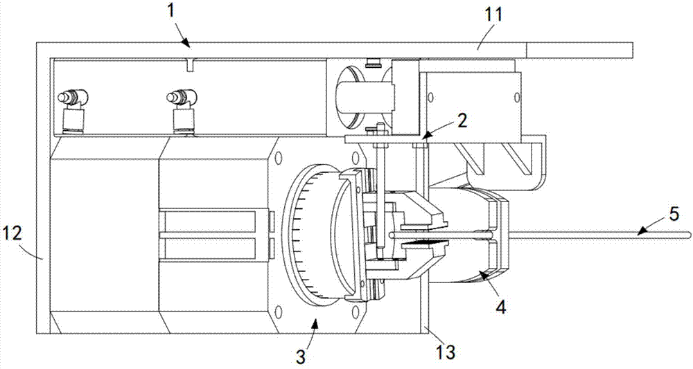
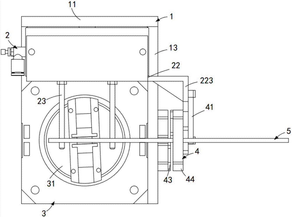
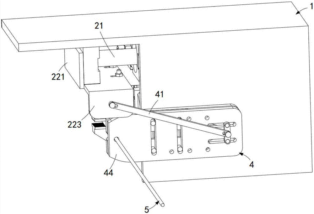
[0046] Such as figure 1 As shown, a continuous shearing and bending integrated machine for binding iron wire includes a mounting plate 1, the mounting plate 1 includes a first mounting portion 11, and a second mounting portion 12 vertically arranged to the first mounting portion 11, respectively. With the third installation part 13, the first installation part 11 is located at the top of the installation board 1, the second installation part 12 is located at the rear side of the first installation part 11, and the third installation part 13 is located at the top of the installation board 1. The right side of the first installation part 11 also includes:

[0047] Bending assembly 2, described bending assembly 2 is installed on the described first mounting part 11, and it carries out bending work to iron wire 5;

[0048] Clamping assembly 3, described clamping assembly 3 is installed on the described second mounting part 12, and it is positioned at the directly below described ...


PUM


Abstract

The invention discloses an iron wire continuous cutting and bending all-in-one machine for bundling. The iron wire continuous cutting and bending all-in-one machine comprises a bending assembly, a clamping assembly and a cutting assembly. Through linkage arrangement of the bending assembly and the cutting assembly, iron wires penetrate through the cutting assembly and then are clamped on the clamping assembly, a bending rod and the cutting assembly are driven by an air cylinder to conduct linkage operation, the iron wires are cut through the cutting assembly at first, the cutting assembly is reset through a reset spring, then the bending rod applies radial acting force to the iron wires to bend the iron wires, the technical problem that iron wires need to be bent manually after being cut in the background art is solved, and the structure is simple.

Description

technical field [0001] The invention relates to the technical field of iron wire shearing, in particular to an integrated machine for continuous shearing and bending of iron wires for binding. Background technique [0002] In production and life, it is often necessary to bind items with iron wires. At this time, the iron wires need to be cut into sections. At present, the iron wire shearing mechanism usually adopts a structure composed of cranks and sliders. This structure is more convenient to operate. , at the same time, the structure can be operated continuously and uninterruptedly through the crank, and the iron wire can be cut. At the same time, this structure can be connected with the electromagnetic clutch, so that this structure can be produced automatically, but this structure is not conducive to installation in assembly line production equipment. The cut iron wire needs to be put into the bending and buckling mechanism with other equipment, which will greatly reduc...

Claims


Application Information

Patent Timeline
Patent Type & Authority Applications(China)
IPC IPC(8): B21F11/00B21F1/00
Inventor 杨越民
Owner FOSHAN ZHIDA SIJIA ELECTRICAL & MECHANICAL TECH CO LTD
Why Eureka
Try Eureka