

Low-conductivity micro-sensor and method for applying same
A micro-sensor, low-conductivity technology, used in fluid resistance measurement and other directions, can solve problems such as weak ability to shield external signals, and achieve the effects of improving anti-pollution ability, good shielding effect, and simple structure
- Summary
- Abstract
- Description
- Claims
- Application Information
AI Technical Summary
Problems solved by technology
Method used
Image

Examples
Embodiment Construction
[0024] The present invention will be further described below in conjunction with the accompanying drawings. The following examples are only used to illustrate the technical solution of the present invention more clearly, but not to limit the protection scope of the present invention.
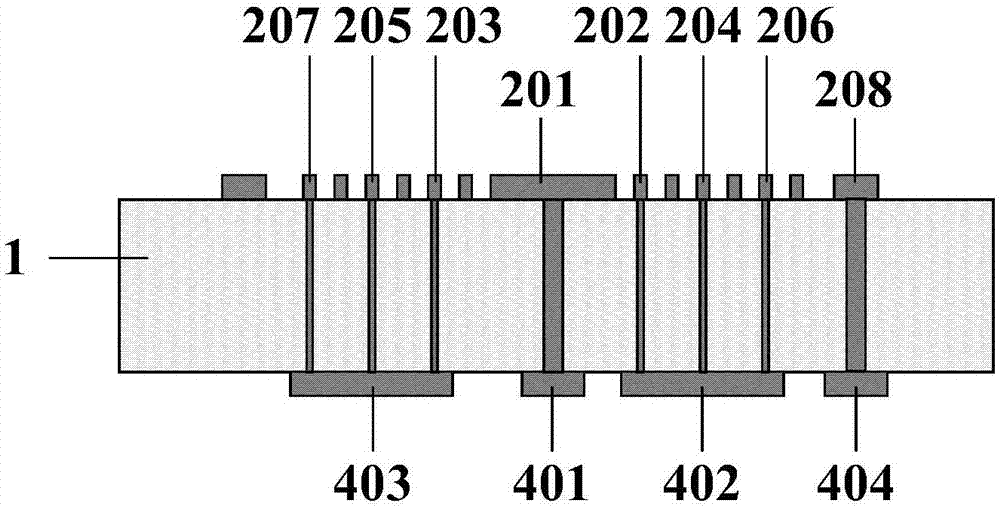
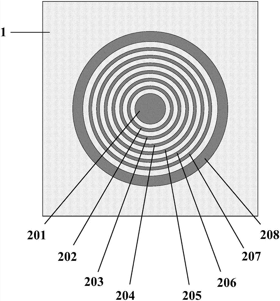
[0025] A kind of low conductivity microsensor, it is characterized in that: comprise substrate 1, circular current electrode 201, annular voltage electrode, annular ground electrode 208 and electrode pad; Described current electrode 201, voltage electrode and ground electrode 208 are concentrically arranged on On the same surface of the substrate 1, there are current electrodes 201, voltage electrodes and ground electrodes 208 from inside to outside; the electrode pads are arranged on the electrode opposite surface of the substrate 1; A through hole; the axes of the through holes are coplanar, and leads are filled in the through holes; the leads are connected to each electrode and each electrode...
PUM
 Abstract
Description
Claims
Application Information