Controller and generator-motor starting method

A technology for generating motors and control devices, which is applied in the direction of controlling generators, motor generators/starters, starters of single multi-phase induction motors, etc., and can solve the problem of inability to increase the speed of variable-speed generator motors, reduce the speed, and increase machine costs And other issues

Active Publication Date: 2018-01-12
KK TOSHIBA
View PDF7 Cites 0 Cited by
  • Summary
  • Abstract
  • Description
  • Claims
  • Application Information

AI Technical Summary

Problems solved by technology

Therefore, the output frequency range and output voltage range of the frequency converter used as the excitation device are also reduced in proportion to the variable speed operating range. Connected to the secondary excitation device and used as a starter to supply driving power, the output voltage is also low, so it becomes impossible to increase the speed of the variable speed generator motor to the target speed that can be synchronized with the system
[0006] For such problems, in addition to (1) the method of additionally installing a thyristor starting device (thyristor starting method) as described at the beginning, it is also considered to apply (2) to install a branch circuit bus bar with a large current, a disconnector, etc., in The main circuit is switched at startup, and the required driving power is injected from the primary winding side of the generator motor (self-starting method (primary side)), (3) The step-up transformer used only at startup and the branch circuit bus, The isolating switch is installed on the secondary winding side to boost the secondary voltage at start-up and inject the required driving power from the secondary winding side (self-starting method (secondary side step-up transformer attached)). In the case of any of these methods, since a large device / machine is additionally installed, the cost of the machine is increased, the layout design of the power plant is complicated, and it leads to an increase in the size of the building and an increase in the construction cost.

Method used


Image

  • Controller and generator-motor starting method
  • Controller and generator-motor starting method
  • Controller and generator-motor starting method

Examples


Embodiment Construction

[0016] Embodiments will be described below with reference to the drawings.

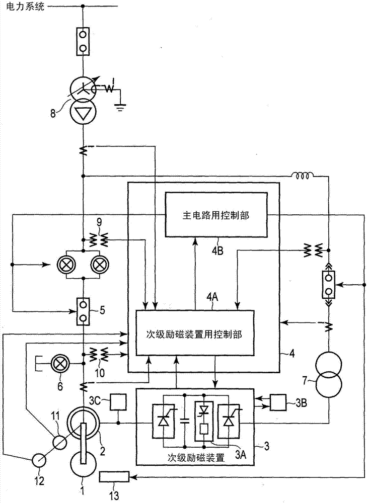
[0017] figure 1 It is a block diagram showing the basic configuration of the variable-speed pumping power generation system according to the embodiment.

[0018] The variable-speed pumping power generation system has as the main elements: a pump wheel 1; a variable-speed generator motor 2 realized by a double-fed alternator; A self-excited secondary excitation device 3 realized by a frequency converter; a control unit 4A for the secondary excitation device that controls the AC voltage, current, frequency, and phase output from the secondary excitation device 3 and a switching device 5 , the control device 4 that the main circuit of the on-off control of 6, the driving control of the water surface depressing device 13 etc. constitutes with the control part 4B; The isolating switch (corresponding to Japanese: starting circuit breaker) 6 for the three-phase short circuit of the stator winding end of th...


PUM


Abstract

According to an embodiment, there is provided a controller (4) for performing control to supply driving electricity to a secondary winding of a generator-motor (2) from a secondary exciter (3) and thereby start the generator-motor (2) from a standstill state. The controller (4) includes a setting change unit (43) configured to change or cancel, for starting the generator-motor (2), at least one ofa setting of a direct-current circuit voltage of the secondary exciter (3) and a setting of control or protection preset for the direct-current circuit voltage or an output voltage of the secondary exciter (3).

Description

[0001] This application is based on Japanese Patent Application No. 2016-133331 (filing date: July 5, 2016), and enjoys priority rights based on this application. This application includes the entire content of the same application by referring to this application. technical field [0002] Embodiments of the present invention relate to a control device and a method for starting a generator motor that control startup of a generator motor in a pumping power generation system or the like. Background technique [0003] As a starting device for a generator motor in a large-capacity pumping power station, a static starting device is generally used. The static starting device uses a frequency converter composed of semiconductor elements, and adopts the following method: accelerate from a stop state to a rated rotation speed, and obtain After the system voltage is synchronized with the terminal voltage of the generator motor, the system is integrated through a circuit breaker for pa...

Claims


Application Information

Patent Timeline
Patent Type & Authority Applications(China)
IPC IPC(8): H02P9/04
CPCH02P1/26H02P9/007H02P9/08
Inventor 石月照之影山隆久
Owner KK TOSHIBA
Why Eureka
Try Eureka