
Network load balancing device and method

A technology of a network load and balancing device, applied in the field of network communication, can solve the problems of increasing migration overhead and communication delay, not considering flow scheduling delay, etc., and achieves the effect of improving network utilization efficiency and reducing scheduling cost.

Active Publication Date: 2018-01-12
BEIJING INFORMATION SCI & TECH UNIV
View PDF4 Cites 16 Cited by
  • Summary
  • Abstract
  • Description
  • Claims
  • Application Information

AI Technical Summary

Problems solved by technology

These algorithms are divided into two categories: one type of algorithm is to formulate the best virtual machine (VM) migration strategy from the perspective of the server, according to the load of the server's CPU, storage, and bandwidth resources, thereby achieving server load balancing, but this is in the realization While balancing the load, it also increases the migration overhead and communication delay; another type of algorithm is to formulate static and dynamic rerouting strategies based on the statistical link state information from the network point of view, and dispatch the traffic in the congested link to the remaining In the link with the largest bandwidth, the load balancing of the link is realized and the utilization rate of the link is improved, but this algorithm does not consider the delay caused by flow scheduling

Method used


Image

  • Network load balancing device and method
  • Network load balancing device and method
  • Network load balancing device and method

Examples


Embodiment Construction

[0024] The following description with reference to the accompanying drawings is provided to assist in a comprehensive understanding of exemplary embodiments of the present invention as defined by the claims and their equivalents. The description includes various specific details to assist in that understanding, but these details are to be regarded as examples only. Accordingly, those of ordinary skill in the art will recognize that various changes and modifications of the embodiments described herein can be made without departing from the scope and spirit of the invention. Also, descriptions of well-known functions and constructions may be omitted for clarity and conciseness.

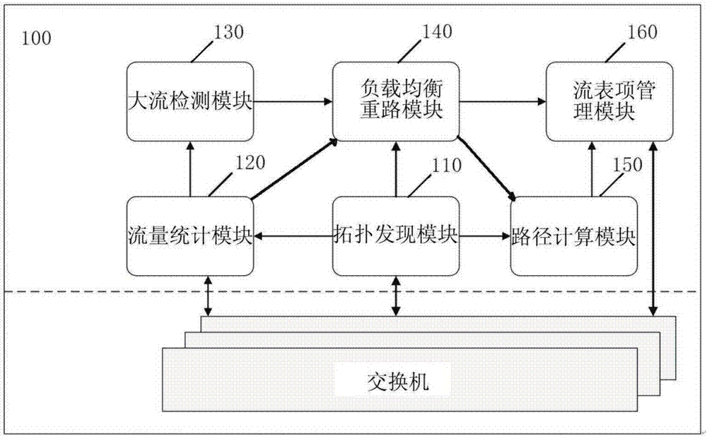
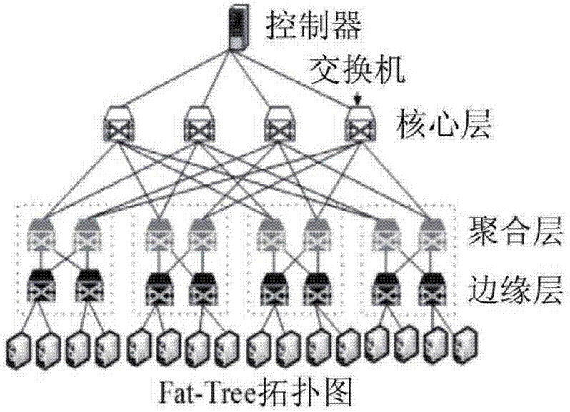
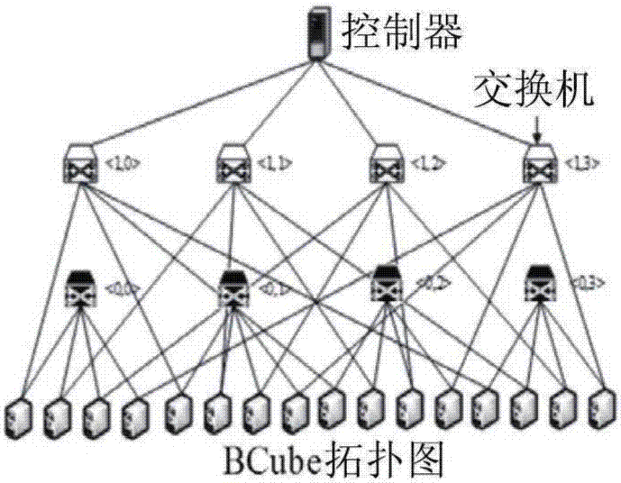
[0025] figure 1 is a block diagram illustrating a network load balancing device 100 according to an exemplary embodiment of the present invention. Figure 2a and Figure 2b is an example showing a network topology to which the network load balancing apparatus and method according to the exemplary emb...


PUM


Abstract

The invention provides a network load balancing device and method. The device comprises a topology discovery module, a traffic statistics module, a large flow monitoring module, a load balancing rerouting module and a path calculation module, wherein the topology discovery module is configured to acquire network topology information and network parameter information, and the network parameter information includes energy consumption information of each switch in a network and capacity information of each link in the network; the traffic statistics module is configured to acquire network trafficinformation; the large flow monitoring module is configured to determine a large flow and a small flow on each link based on the network traffic information; the load balancing rerouting module is configured to calculate the load balancing degree of the links in the network based on the network topology information, the network parameter information and the network traffic information to determine an overload link; and the path calculation module is configured to determine a scheduling path of the large flow in the overload link based on the energy consumption information of the switches in the network and the network traffic information and form a new flow table.

Description

technical field [0001] The present application relates to the field of network communication, and more specifically, relates to a dynamic load balancing device and method in a data center network. Background technique [0002] With the rapid development of new Internet technologies and services such as mobile Internet, cloud computing, and big data, and the emergence of Internet services with high bandwidth consumption, the network structure that relies solely on high-performance data centers has been unable to provide services for users widely distributed around the world. Reliable quality of service. Moreover, the traditional OSPF (Open Shortest Path First) routing algorithm will select a single shortest path as the final path, which may cause most network flows to concentrate on a single path and cause network congestion, which cannot make full use of the DCN (Data Center Network) link resources. In addition, the single-path TCP transmission mechanism based on distribut...

Claims


Application Information

Patent Timeline
Patent Type & Authority Applications(China)
IPC IPC(8): H04L12/803H04L12/721H04L12/751H04L45/02
Inventor 周金和位明扬
Owner BEIJING INFORMATION SCI & TECH UNIV
Learn More