Puncture point locating device and puncture point locating method

A positioning device and puncture point technology, which is applied in the field of medical devices, can solve the problems of decreased positioning accuracy, offset of marking positions, and reduced surgical efficiency, so as to achieve the effects of improving positioning accuracy, reducing operation time, and improving surgical efficiency

Active Publication Date: 2018-01-16
SHANGHAI UNITED IMAGING HEALTHCARE
View PDF5 Cites 14 Cited by
  • Summary
  • Abstract
  • Description
  • Claims
  • Application Information

AI Technical Summary

Problems solved by technology

[0003] However, when using this method for positioning, there are the following problems: 1) The position of the metal grid can only be placed by the doctor's visual inspection, and it cannot be ensured that it is within the range of the ray beam, which will lead to additional times of perspective; 2) The metal grid cannot do it 3) The distance between the metal grid and the surface of the detector is relatively long, and the X-rays emitted by the X-ray source component have a certain cone angle, which causes the metal grid to be projected onto the surface of the detector. The image of the detector is affected by the magnification, and the positioning accuracy will decrease
The above positioning process not only brings more radiation damage to the patient's body, but also the operation of fixing the copper mesh for many times also brings inconvenience to the doctor's work, reduces the doctor's work efficiency and also reduces the operation efficiency

Method used


Image

  • Puncture point locating device and puncture point locating method
  • Puncture point locating device and puncture point locating method
  • Puncture point locating device and puncture point locating method

Examples


Embodiment Construction

[0042] In order to make the technical problems solved by the present invention, the technical solutions adopted and the technical effects achieved clearer, the technical solutions of the embodiments of the present invention will be further described in detail below in conjunction with the accompanying drawings. Obviously, the described embodiments are only the technical solutions of the present invention. Some, but not all, embodiments. Based on the embodiments of the present invention, all other embodiments obtained by those skilled in the art without creative efforts fall within the protection scope of the present invention.

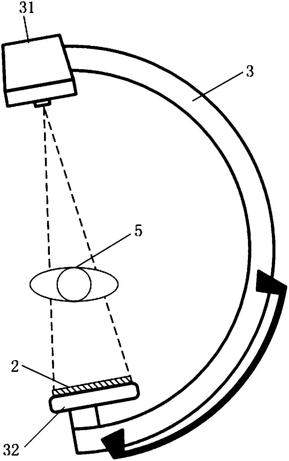
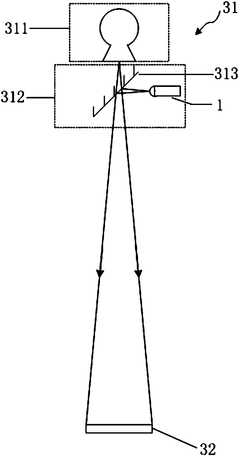
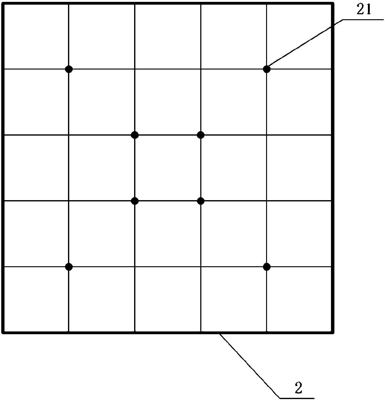
[0043] This embodiment provides a preferred puncture point positioning device for a C-arm X-ray machine, the C-arm X-ray machine includes a C-arm frame 3, and one end of the C-arm frame 3 is an X-ray source end 31, used to emit X-rays, and the other end is a detector end, which is provided with a detector 32 for collecting X-rays and forming an image, ...


PUM


Abstract

The invention discloses a puncture point locating device, and relates to the technical field of medical apparatuses. The locating device comprises a locating part and a laser transmitter, wherein thelocating part is located between a detector and an examination area, the locating part is grid-shaped, an X-ray image formed by superimposing images of the locating part and a target object can be obtained after X-rays penetrate through the locating part, the laser transmitter is used for projecting a grid-shaped pattern to the examination area, and the grid-shaped pattern corresponds to the imageof the locating part in the X-ray image. The invention discloses a puncture point locating method adopting the puncture point locating device. According to the puncture point locating device and thepuncture point locating method, laser beams with the grid-shaped pattern and the grid-shaped locating part are utilized to assist a doctor in locating puncture points of the body surface, the locatingprecision is improved, the operation time is shortened, the frequency of fluoroscopy of a C-shaped arm X-ray machine is reduced, and the radiation dosage during an operation is reduced.

Description

technical field [0001] The invention relates to the technical field of medical devices, in particular to a puncture point positioning device and a puncture point positioning method. Background technique [0002] In minimally invasive orthopedic surgery, doctors need to use X-ray fluoroscopy images to locate the location of the lesion, so as to estimate the needle insertion site. In order to facilitate the determination of the needle insertion site, the method commonly used in the prior art is: make the fine copper wire into a grid-like structure, and set some marks on the grid. Then attach the copper mesh to the body surface, use the C-arm to expose, observe the position of the bone through the X-ray film carrying the position information of the copper mesh, and use the relative position information of the bone and the copper mesh to determine the puncture point on the body surface. [0003] However, when using this method for positioning, there are the following problems: ...

Claims


Application Information

Patent Timeline
Patent Type & Authority Applications(China)
IPC IPC(8): A61B17/34A61B90/13
Inventor 印晖赵庆军
Owner SHANGHAI UNITED IMAGING HEALTHCARE
Why Eureka
Try Eureka