
Vision positioning guiding device and guiding method

A visual positioning and guiding device technology, applied in the field of visual positioning, can solve problems such as the inability to meet the needs of large field of view and high-precision positioning, and achieve the effect of meeting the needs of precise visual positioning and guidance

Active Publication Date: 2018-01-16
上海赛摩电气有限公司
View PDF5 Cites 30 Cited by
  • Summary
  • Abstract
  • Description
  • Claims
  • Application Information

AI Technical Summary

Problems solved by technology

[0005] Especially for large-scale equipment assembly lines, conventional machine vision positioning and guidance devices and methods cannot meet the large field of view and high-precision positioning requirements

Method used


Image

  • Vision positioning guiding device and guiding method
  • Vision positioning guiding device and guiding method
  • Vision positioning guiding device and guiding method

Examples


Embodiment Construction

[0060] The present invention will be further described in detail below in conjunction with the accompanying drawings, so that those skilled in the art can implement it with reference to the description.

[0061] It should be understood that terms such as "having", "comprising" and "including" as used herein do not entail the presence or addition of one or more other elements or combinations thereof.

[0062] The technical solution of the present invention is described in detail by applying the device and method of the present invention to the automatic copper pipe of the central air-conditioning chiller as a specific embodiment.

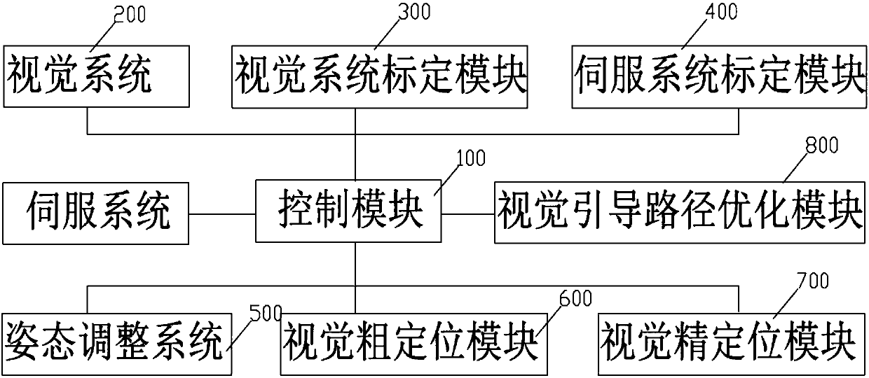
[0063] The present invention provides a visual positioning guidance device, such as figure 1 As shown, it includes a control module 100 and a vision system 200 respectively connected to the control module 100, a vision system calibration module 300, a servo system calibration module 400, an attitude adjustment system 500, a vision rough positioning m...


PUM


Abstract

The invention discloses a vision positioning guiding device and guiding method. The device includes a visual system, a visual system calibration module, a servo system calibration module, a vision rough positioning module, a vision precise positioning module, a vision guiding path optimization module and a PLC communication interaction module and the like. Precise calibration of the vision systemand a servo system and precise positioning guiding and guiding path optimization in the industrial automation assembly process are achieved, precise positioning guiding requirements in the industrialautomation assembly process can be met, high positioning precision is achieved particularly for large industrial assembly, and the requirements of accurate visual positioning guiding in the industrialautomation assembly process are met.

Description

technical field [0001] The present invention relates to the technical field of visual positioning, and more specifically, the present invention relates to a visual positioning guiding device and a guiding method. Background technique [0002] In a modern automated assembly line, the "grab-and-place" assembly action is usually completed by an industrial robot or a servo system. In order to complete the assembly task, it is necessary to obtain the positioning information of the manipulated object. First, the robot or servo system must know the pose of the object before it is manipulated to ensure that the robot can grasp it accurately; secondly, it must know the target of the manipulated object. pose to ensure that the robot completes the task accurately. In most applications, the robot or servo system only operates according to a fixed program, the initial pose and end pose of the object are specified in advance, and the quality of task completion is guaranteed by the positi...

Claims


Application Information

Patent Timeline
Patent Type & Authority Applications(China)
IPC IPC(8): B23P19/00G06T7/00G06T7/73G06T7/80
Inventor 于福江杨卓峰刘敏
Owner 上海赛摩电气有限公司
Learn More