Wheel noise reduction method and multi-layer type wheel noise reduction block
A multi-layer, wheel technology, applied in the field of wheel vibration reduction and noise reduction, can solve the problems of no vibration degree of freedom, rubber shear effect, and limitation of vibration and noise reduction technology effects, so as to achieve good wheel axial vibration and noise, and realize Fast and accurate positioning, avoiding the effect of welding deformation
- Summary
- Abstract
- Description
- Claims
- Application Information
AI Technical Summary
Problems solved by technology
Method used
Image
Examples
Embodiment 1
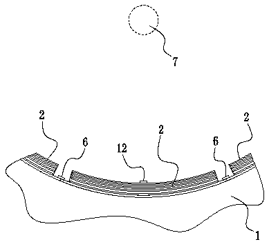
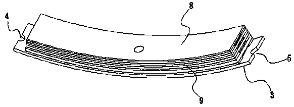
[0039] Embodiment 1: as Figure 1 to Figure 4 Shown, a kind of wheel noise reduction method, it is to arrange multilayer type wheel noise reduction block 2 on the circumferential inner side of wheel 1 to carry out vibration reduction and noise reduction, in multilayer type wheel noise reduction block 2 close to the wheel 1 A mounting plate 3 is arranged on one side of the inner side of the circumference, and a hole 4 and a hole 5 are respectively arranged at both ends of the mounting plate 3, and the two end bolts 6 are screwed through the hole 4 and the hole 5 respectively. Into the circumferential inner side of the wheel 1, so that the two ends of the multi-layer wheel noise reduction block 2 are connected to the wheel 1, and the first outer ring is arranged on the side of the multi-layer wheel noise reduction block 2 near the wheel shaft 7. A constrained layer 8, a suspended inner constrained layer 9 is set between the mounting plate 3 and the first outer constrained layer ...
Embodiment 2
[0053] Embodiment 2: as Figure 5 As shown, compared with Example 1, the difference is that the suspended inner constraining layer 9 is a single-layer structure.
Embodiment 3
[0054] Embodiment 3: as Figure 6 As shown, compared with Embodiment 1, the difference is that an axial extension 101 is provided on the other end of the mandrel 10, so that the other end of the mandrel 10 forms a circular boss shape, and at the first The outer constraining layer 8 is provided with a through hole 14 matching the axial extension 101, and the axial extension 101 is inserted into the through hole 14 to closely fit with the through hole 14, so that one end of the mandrel 10 In contact with the first outer constraining layer 8 . The axial protruding part cooperates with the through hole to play the role of installation and positioning. The mounting plate 3 is provided with a positioning groove 15 matched with one end of the mandrel. When assembling, one end of the mandrel is inserted into the positioning groove and closely matched with the positioning groove, which can further facilitate the installation and positioning of the product. Here, an axial protruding p...
PUM
 Abstract
Description
Claims
Application Information
 - R&D
- Intellectual Property
- Life Sciences
- Materials
- Tech Scout
- Unparalleled Data Quality
- Higher Quality Content
- 60% Fewer Hallucinations
Browse by: Latest US Patents, China's latest patents, Technical Efficacy Thesaurus, Application Domain, Technology Topic, Popular Technical Reports.
© 2025 PatSnap. All rights reserved.Legal|Privacy policy|Modern Slavery Act Transparency Statement|Sitemap|About US| Contact US: help@patsnap.com


