Intermittent feeding device for carbon dust

A feeding device and toner technology, which is applied in the directions of transportation, packaging, loading/unloading, etc., can solve the problems that the toner is easy to stick to the discharge pipe, difficult to do quantitative feeding, and easy to block the discharge port.

Active Publication Date: 2018-01-16
珠海征图打印耗材有限公司
View PDF7 Cites 19 Cited by
  • Summary
  • Abstract
  • Description
  • Claims
  • Application Information

AI Technical Summary

Problems solved by technology

[0005] In order to overcome the shortcomings of the existing carbon powder feeding device that it is difficult to quantitatively feed the material, the carbon powder is poured into the device in a large amount and the disc

Method used


Image

  • Intermittent feeding device for carbon dust
  • Intermittent feeding device for carbon dust
  • Intermittent feeding device for carbon dust

Examples


Embodiment 1

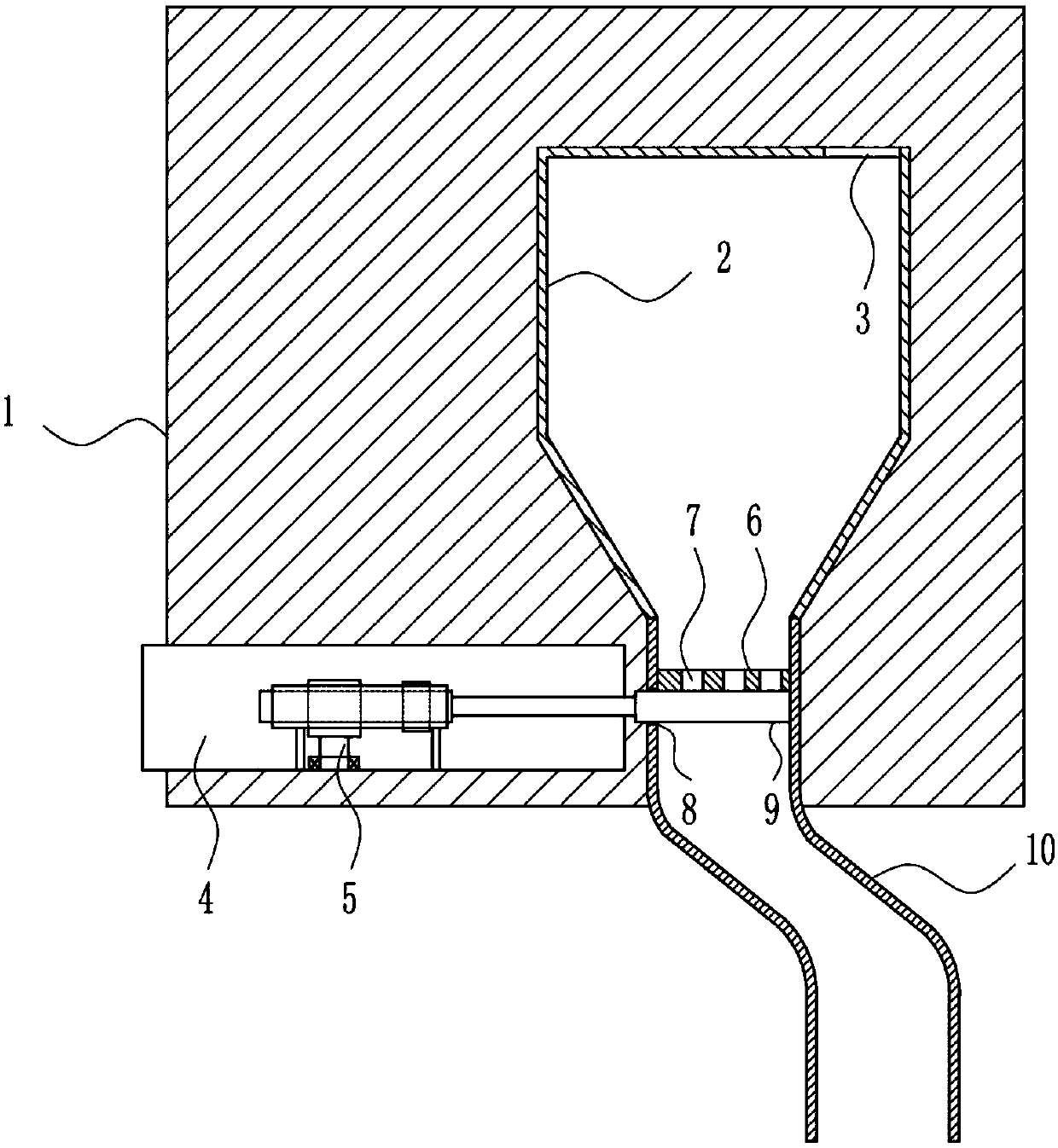
[0034] A carbon powder intermittent feeding device, such as Figure 1-7 As shown, it includes a mounting plate 1, a box body 2, a driving mechanism 4, a blanking mechanism 5, a baffle plate 6, a first connecting plate 9 and a discharge pipe 10, and the right side of the front wall of the mounting plate 1 is provided with a box body 2, The left side of the front wall of the mounting plate 1 is provided with a driving mechanism 4 and a blanking mechanism 5, the driving mechanism 4 is positioned at the rear of the blanking mechanism 5, the right side of the blanking mechanism 5 is provided with a first connecting plate 9, and the right side of the top of the box body 2 has a The first through hole 3, the bottom of the casing 2 is provided with a discharge pipe 10, the upper part of the left wall of the discharge pipe 10 has a third through hole 8, and a baffle plate 6 is arranged between the left and right walls of the top of the discharge pipe 10, and the baffle plate The second...

Embodiment 2

[0036] A carbon powder intermittent feeding device, such as Figure 1-7 As shown, it includes a mounting plate 1, a box body 2, a driving mechanism 4, a blanking mechanism 5, a baffle plate 6, a first connecting plate 9 and a discharge pipe 10, and the right side of the front wall of the mounting plate 1 is provided with a box body 2, The left side of the front wall of the mounting plate 1 is provided with a driving mechanism 4 and a blanking mechanism 5, the driving mechanism 4 is positioned at the rear of the blanking mechanism 5, the right side of the blanking mechanism 5 is provided with a first connecting plate 9, and the right side of the top of the box body 2 has a The first through hole 3, the bottom of the casing 2 is provided with a discharge pipe 10, the upper part of the left wall of the discharge pipe 10 has a third through hole 8, and a baffle plate 6 is arranged between the left and right walls of the top of the discharge pipe 10, and the baffle plate The second...

Embodiment 3

[0039] A carbon powder intermittent feeding device, such as Figure 1-7 As shown, it includes a mounting plate 1, a box body 2, a driving mechanism 4, a blanking mechanism 5, a baffle plate 6, a first connecting plate 9 and a discharge pipe 10, and the right side of the front wall of the mounting plate 1 is provided with a box body 2, The left side of the front wall of the mounting plate 1 is provided with a driving mechanism 4 and a blanking mechanism 5, the driving mechanism 4 is positioned at the rear of the blanking mechanism 5, the right side of the blanking mechanism 5 is provided with a first connecting plate 9, and the right side of the top of the box body 2 has a The first through hole 3, the bottom of the casing 2 is provided with a discharge pipe 10, the upper part of the left wall of the discharge pipe 10 has a third through hole 8, and a baffle plate 6 is arranged between the left and right walls of the top of the discharge pipe 10, and the baffle plate The second...


PUM


Abstract

The invention relates to a feeding device, in particular to an intermittent feeding device for carbon dust. The technical problems are solved with the intermittent feeding device. The intermittent feeding device comprises an installation plate, a box body, a driving mechanism, a discharging mechanism, a baffle and others; the box body is arranged on the right side of the front wall of the installation plate, the driving mechanism and the discharging mechanism are arranged on the left side of the front wall of the installation plate, the driving mechanism is located behind the discharging mechanism, a first connecting plate is arranged on the right side of the discharging mechanism, a first through hole is formed in the right side of the top of the box body, a discharging pipe is arranged at the bottom of the box body, a third through hole is formed in the upper portion of the left wall of the discharging pipe, and the baffle is arranged between the left wall and the right wall of the upper portion of the discharging pipe. The intermittent feeding device can achieve intermittent quantified feeding, the carbon dust can be prevented from blocking a discharging port and adhering to thedischarging pipe, the first connecting plate can intermittently control the carbon dust to flow into the discharging pipe with the discharging mechanism, and the device is high in practicability.

Description

technical field [0001] The invention relates to a feeding device, in particular to a carbon powder intermittent feeding device. Background technique [0002] Toner, its main component is not carbon, but most of it is composed of resin, carbon black, charging agent, magnetic powder, etc., the toner is melted into the paper fiber at high temperature, and the resin is oxidized into a gas with a pungent smell. The so-called 'ozone', this gas has only one benefit, which is to protect the earth and reduce the harm of solar radiation. It is not good for the human body itself, but it will cause irritation to the human mucous membrane, and it is easy to increase the incidence of asthma or nasal allergies, and even dizziness. , vomiting and so on. [0003] The existing toner feeding device has the disadvantages that it is difficult to quantitatively feed the material, the toner is poured into the device in large quantities and it is easy to block the discharge port, and the toner is ...

Claims


Application Information

Patent Timeline
IPC IPC(8): B65G65/40
Inventor 高佳盛肖程聚王静
Owner 珠海征图打印耗材有限公司
Why Eureka
Try Eureka