Structure and construction method of T-beam prefabricated field pedestals

A technology of prefabrication yards and pedestals, which is applied in the direction of infrastructure engineering, manufacturing tools, auxiliary molding equipment, etc. It can solve the problems of pedestals without anti-leakage slurry, foundation subsidence, and inability to discharge, so as to achieve convenient adjustment of height difference and accurate placement , the effect of preventing template offset

Pending Publication Date: 2018-01-16
CHINA THIRD METALLURGICAL GRP
View PDF7 Cites 2 Cited by
  • Summary
  • Abstract
  • Description
  • Claims
  • Application Information

AI Technical Summary

Problems solved by technology

[0002] At present, the design of the prefabricated pedestal of the T-beam is unreasonable, the foundation is not properly treated, and there is no drainage design. During the rainy season or during the maintenance of the T-beam, too much water cannot be drained out, resulting in foundation subsidence
In addition, the pedestal has no anti-leakage design, and at the same time, the connection between the prefabricated formwork of the T-beam and the pedestal is not stable. When pouring the T-beam, it is easy to cause defects in the prefabricated T-beam structure.

Method used


Image

  • Structure and construction method of T-beam prefabricated field pedestals
  • Structure and construction method of T-beam prefabricated field pedestals
  • Structure and construction method of T-beam prefabricated field pedestals

Examples


Embodiment Construction

[0030] The present invention will be described in detail below in conjunction with the accompanying drawings, but it should be pointed out that the implementation of the present invention is not limited to the following embodiments.

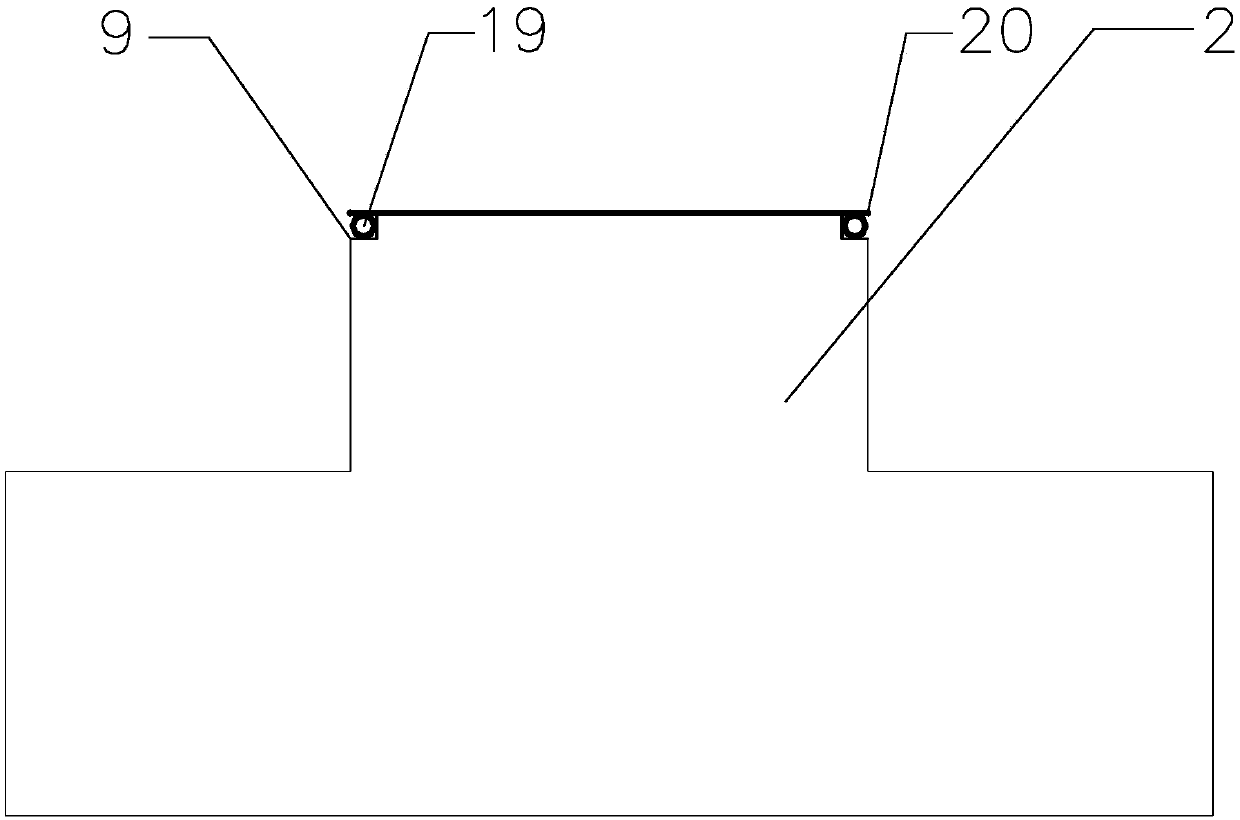
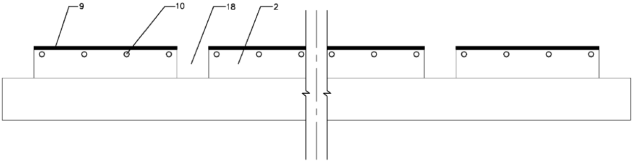
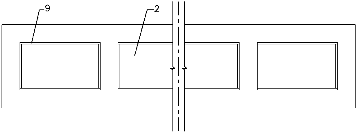
[0031] Such as Figure 1-Figure 8 As shown, a T-beam prefabricated field pedestal structure is provided with an anti-leakage slurry device at the upper end of the pedestal 2; on the top of the pedestal 2, a pipeline 10 is pre-embedded for the T-beam side formwork tension bolts; Bottom mold brackets are provided at the suspension beams 18 between the pedestals 2; drainage grooves are provided on the basis of the pedestals 2.

[0032] The anti-leakage slurry device includes a ring support beam 9 and a sealing rubber hose 19. The ring support beam 9 is welded end to end by angle steel on the top of the pedestal 2, and the ring support beam 9 forms a rubber hose on the top of the pedestal 2. The installation groove, the sealing rubber hose 19 is pla...


PUM


Abstract

The invention provides a structure and construction method of T-beam prefabricated field pedestals. A leak-proof slurry device is arranged at the upper ends of the pedestals; a T-beam side formwork split bolt reserving pipe is pre-buried in the upper parts of the pedestals; a bottom mould support device is arranged on a hanging beam between the pedestals; drain grooves are formed in the bases of the pedestals. The structure and construction method of the T-beam prefabricated field pedestals have the advantages that the close fit between a T-beam bottom mould and a side mould is achieved through a sealing rubber pipe in the leak-proof slurry device, the phenomena of leakage, honeycomb and pitted surface occurred in the T-beam pouring process are avoided, the robustness and adherence of theT-beam template are strengthened through the arrangement of the T-beam side formwork split bolt reserving pipe, and a strong fixing effect is achieved for preventing the offset and leakage of the formwork. The bottom mould support device at the position of the hanging beam is convenient to move and can be reused. The height difference can be conveniently adjusted through a screw adjusting rod, andthe placement position is accurate. Drainage can be quickly achieved through the design of a drainage system, the phenomenon of water ponding does not exist, and the construction is not affected.

Description

technical field [0001] The invention relates to a bridge prefabrication field, in particular to a platform structure and a construction method of a T-beam prefabrication field. Background technique [0002] At present, the design of the prefabricated pedestal of the T-beam is unreasonable, the foundation is not properly treated, and there is no drainage design. During the rainy season or during the maintenance of the T-beam, too much water cannot be drained out, resulting in foundation subsidence. In addition, the pedestal has no anti-leakage design, and the connection between the prefabricated formwork of the T-beam and the pedestal is not stable, and it is easy to cause defects in the prefabricated T-beam structure to leak when pouring the T-beam. When there is little slurry leakage, the phenomenon of "burrs" will appear on the bottom edge, and when it is serious, there will be honeycomb pitting. In order to solve the above problems, a T-beam prefabricated pedestal struct...

Claims


Application Information

Patent Timeline
Patent Type & Authority Applications(China)
IPC IPC(8): E02D27/44E02D31/06B28B17/00
Inventor 宿巳光宋秀成王虎成徐英超
Owner CHINA THIRD METALLURGICAL GRP
Why Eureka
Try Eureka