
Air conditioner fan achieving air incoming from two side faces simultaneously

An air-conditioning fan, side entry technology, applied in air-conditioning systems, space heating and ventilation, heating and ventilation hoods/covers, etc., can solve the problems of insignificant local cooling effect, difficult machine cleaning, and inability to perform air purification at the same time, To achieve the effect of good water evaporation cooling or humidification, saving purchase costs, and convenient cleaning

Pending Publication Date: 2018-01-16
SHENZHEN LIANCHUANG ELECTRICAL APPLIANCE IND CO LTD
View PDF18 Cites 1 Cited by
  • Summary
  • Abstract
  • Description
  • Claims
  • Application Information

AI Technical Summary

Problems solved by technology

[0004] The technical problem to be solved by the present invention is to avoid the disadvantages of the prior art that the local cooling effect of the air-conditioning fan for local humidification and cooling in the room is not obvious, and it is difficult to clean the inside of the machine and the air cannot be purified at the same time. The air-conditioning fan of the wind; use the self-absorbing water evaporation carrier assembly set at both ends to cooperate with the fan assembly to produce a better water evaporation cooling effect, and the water evaporation carrier assembly and the water tank are very convenient to disassemble and wash. An air filter can also be set to perform air filtration while humidifying and cooling

Method used


Image

  • Air conditioner fan achieving air incoming from two side faces simultaneously
  • Air conditioner fan achieving air incoming from two side faces simultaneously
  • Air conditioner fan achieving air incoming from two side faces simultaneously

Examples


Embodiment Construction

[0022] The content of the present invention will be further described in detail below in conjunction with each accompanying drawing.

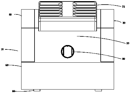
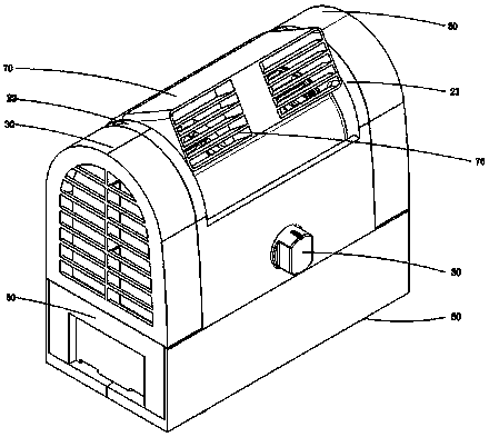
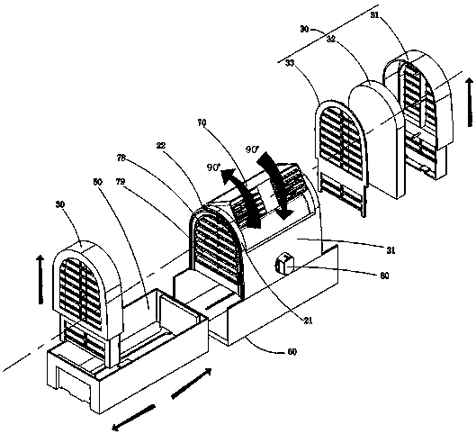
[0023] Such as Figures 1 to 4 The shown air-conditioning fan 10 with air intake from both sides includes: a body assembly 20, a fan assembly 70 for providing wind power, a water storage tank 50 for storing water, and a water evaporation carrier assembly 30 for water evaporation and cooling; The water storage tank 50 is accommodated in the lower part of the body assembly 20; the fan assembly 70 includes an air outlet 76 at the top of the fan assembly and two air inlets 78 at both axial ends of the fan assembly; The assembly 70 is accommodated in the body assembly 20, and the two air inlets 78 are respectively located on the lateral sides of the body assembly 20; the water evaporation carrier assembly 30 is vertically placed in the water storage tank 50 near the end of the water tank The wall part, and its corresponding air inlet 78 is close to...


PUM


Abstract

The invention relates to an air conditioner fan achieving air incoming from two side faces simultaneously. The air conditioner fan comprises a body assembly, a fan assembly, a water storage tank and awater evaporation carrier assembly; the fan assembly comprises an air outlet located in the top of the fan assembly and two air inlets located in the two ends of the fan assembly; the water evaporation assembly is vertically arranged on the portion, close to the water tank end wall part, in the water storage tank and is next to the corresponding air inlet; when the fan assembly works, the negative pressure occurs in the inner air, the outside air is sucked under the action of the negative pressure and passes through the water evaporation carrier assembly and the air inlets and the air outletof the fan assembly in sequence, moisture in the water evaporation carrier assembly is blown away and evaporated into the peripheral air by means of airflow, and air cooling and humidification are achieved. Physical evaporation cooling is conducted through dual-port air incoming; by means of a drawer type water tank and the water evaporation carrier assembly convenient to remove, the cooling efficiency is high, water adding and cleaning are convenient, the air conditioner fan can move part of parts conveniently to serve as an ordinary fan or an air filter fan, the air conditioner fan has multiple purposes, and the use cost is reduced.

Description

technical field [0001] The present invention relates to an air-conditioning device, in particular to an air-conditioning device that cools down by evaporation of water in the air, especially to the air-conditioning device that takes in air from both sides at the same time, referred to as an air-conditioning fan. Background technique [0002] The prior art air-conditioning fans used for indoor local humidification and cooling are deeply loved by consumers such as individuals or office workers because of their small size, low energy consumption, portability and certain decorative value; usually these humidification and cooling effects are achieved by means of The ultrasonic transducer oscillates and atomizes water into ultra-fine ions with a size of 1 to 5 microns. The fan drives the air flow to blow the ultra-fine ions into the room, and emits water mist to evaporate it to achieve the purpose of reducing the indoor temperature. [0003] The existing technology uses ultrasonic...

Claims


Application Information

Patent Timeline
IPC IPC(8): F24F5/00F24F13/28F24F13/20F24F11/89
Inventor 赖伴来庞亚鹏
Owner SHENZHEN LIANCHUANG ELECTRICAL APPLIANCE IND CO LTD
Learn More