Novel flue gas white smoke removal system and method

A flue gas, a new type of technology, applied in the field of pollutant control, can solve the problem of waste of cold energy, etc., to achieve the effect of ensuring whitening, increasing the cooling range, and efficient operation

Pending Publication Date: 2021-06-04
XI AN JIAOTONG UNIV
View PDF7 Cites 0 Cited by
  • Summary
  • Abstract
  • Description
  • Claims
  • Application Information

AI Technical Summary

Problems solved by technology

In the traditional regasification technology (open gasifier, submerged burner), this part of cold energy is completely wasted, and at the same time, a considerable amount of electricity or fuel needs to be consumed to maintain the continuous gasification process

Method used


Image

  • Novel flue gas white smoke removal system and method
  • Novel flue gas white smoke removal system and method

Examples


Embodiment 1

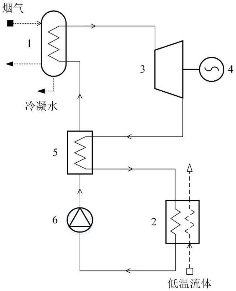
[0032] Such as figure 1 As shown, a new flue gas desipherent system provided by the present invention is composed of a flue gas cooler, a cryogenic fluidizer, a thermal-active / electro-converting subsystem. Among them, the thermal-act / electro-converter system (Example 1 uses a Langken circle) to convert the flue gas low level heat and low temperature fluid cold energy to mechanical energy or electrical energy; the flue gas cooler is reduced by lowering the flue gas temperature and moisture. Flue gas is realized, a heater, as a thermal cycle; a low temperature fluidizer is used to realize the gasification of low temperature fluids as a heat cycle.

[0033] In Example 1, the new flue gas desipherent system consists of flue gas coolers 1, a low temperature fluid gasifier 2, an expander / steam turbine 3, a generator 4, a heat generator 5, a working pump / compressor 6, and related Connection pipeline, bypass circuit, valve, temperature sensor, pressure sensor, etc. Working pump / ...

Embodiment 2

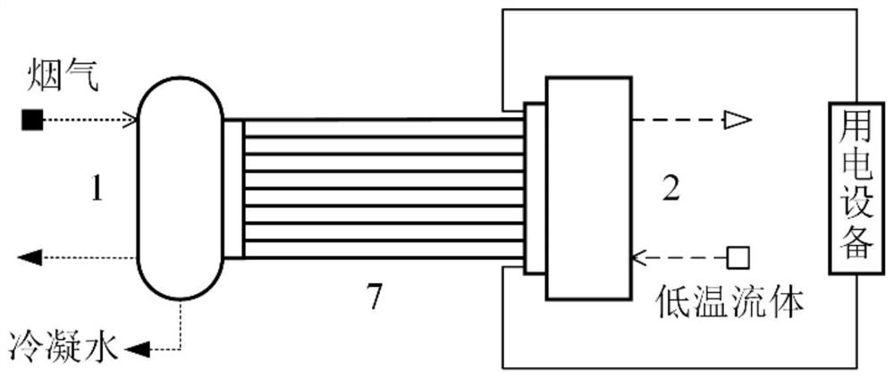
[0035] Such as figure 2 As shown, a new flue gas desipherent system provided by the present invention is composed of a flue gas cooler, a cryogenic fluidizer, a thermal-active / electro-converting subsystem. Among them, the thermal-act / electrical converter system (Example 2 uses a temperature difference generator) to directly convert the flue gas low-grade heat and low temperature fluid cold energy; the flue gas cooler is achieved by reducing flue gas temperature and moisture. Flue gas is despised, as the hot end of the temperature difference power generation equipment; the low temperature fluidizer is used to realize the gasification of the low temperature fluid, as the cold end of the temperature difference power generation equipment.

[0036] In Example 2, the new flue gas desiphery system is consisting of flue gas cooler 1, a low temperature fluidizer 2, a temperature difference generator 7, and a related connection line, a bypass circuit, a valve, a temperature sensor, a pre...


PUM


Abstract

The invention discloses a novel flue gas white smoke removal system and method. The novel flue gas white smoke removal system is composed of three parts, namely a flue gas cooler, a low-temperature fluid gasifier and a heat-power / electricity conversion subsystem. The heat-power / electricity conversion subsystem is used for converting low-grade waste heat of flue gas and cold energy of low-temperature fluid into mechanical energy or electric energy by utilizing a thermodynamic cycle or thermoelectric power generation technology. The flue gas cooler realizes flue gas white smoke removal by reducing the flue gas temperature and the moisture content, and is used as a heater of a thermodynamic cycle or a hot end of thermoelectric power generation equipment. The low-temperature fluid gasifier is used for achieving gasification of low-temperature fluid and serves as a cooler of the thermodynamic cycle or a cold end of the thermoelectric power generation equipment. According to the novel flue gas white smoke removal system and method provided by the invention, the heat-power / electricity conversion subsystem is used for connecting flue gas condensation and white smoke removal with low-temperature fluid gasification, so that direct heat exchange between the flue gas and the low-temperature fluid is avoided, the freezing risk in a heat exchanger is reduced, and the operation safety, the energy utilization efficiency and the economic benefits are improved.

Description

Technical field [0001] The present invention belongs to the field of pollutant governance, and is specifically involved in a new type of flue gas desparability system and method. Background technique [0002] With the increasing pollutant emission standards of domestic power plants, wet smoke is a serious visual pollution source around the city, and it is likely to become a new control indicator after heavily nitrogen oxide, sulfur dioxide, and solid particulate matter. Currently, multi-places have begun to restrict emission initiatives, and the industry has not yet formed a unified standard and technology route. [0003] Wet tobacco feather is mainly because the moisture content in the flue gas is too high, during the air blending process, the temperature is rapidly decreased, and the water vapor reaches a saturated state, and a large amount of water is condensed. Therefore, the prior art is mainly starting from lifting the flue gas temperature and reducing the humidity of the f...

Claims


Application Information

Patent Timeline
Patent Type & Authority Applications(China)
IPC IPC(8): F01K27/00F01K17/02F03G7/04F01K13/00
CPCF01K27/00F01K17/02F03G7/04F01K13/00
Inventor 刘虎于鹏飞周赛薛景文车得福
Owner XI AN JIAOTONG UNIV
Why Eureka
Try Eureka