
A water-cooling-dewhitening device for removing condensable pollutants and recycled water in flue gas

A technology for pollutants and water recycling, applied in the direction of climate sustainability, greenhouse gas reduction, lighting and heating equipment, etc. The effect of large heat exchange area and energy consumption reduction

Active Publication Date: 2020-03-20
FUDAN UNIV
View PDF3 Cites 1 Cited by
  • Summary
  • Abstract
  • Description
  • Claims
  • Application Information

AI Technical Summary

Problems solved by technology

Among these technologies, (1) and (2) did not achieve "white removal", but only made the "white smoke" visually "invisible" and then discharged into the atmosphere without any removal; (3) partial removal could be achieved , the general removal efficiency is about 15%-30%. At the same time, there are technically high investment and maintenance costs, and the pipeline is easy to corrode; (4) Only the escaped droplets produced after desulfurization can be removed efficiently, and wet electrostatic precipitator can be partially realized Function, cannot remove the "white smoke" in the flue gas
Most of the current pilot technologies in the market cannot be "whitened" in principle, and some of them have very low removal efficiency. After the standardization of environmental protection parameters in the future, these technologies will not be able to meet the needs of my country's environmental protection market for "whitening".

Method used


Image

  • A water-cooling-dewhitening device for removing condensable pollutants and recycled water in flue gas
  • A water-cooling-dewhitening device for removing condensable pollutants and recycled water in flue gas
  • A water-cooling-dewhitening device for removing condensable pollutants and recycled water in flue gas

Examples


Embodiment Construction

[0032] In the following, the present invention will be further described in combination with the actual test of the present invention in a coal-fired power plant, but the protection scope of the present invention is not limited thereto.

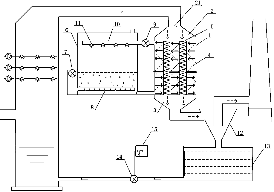
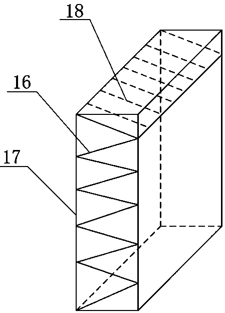
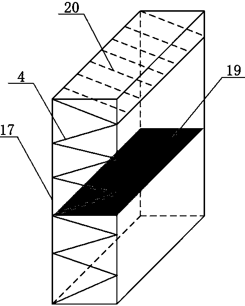
[0033] Such as figure 1 As shown, a water-cooled dewhitening device for removing condensable pollutants in flue gas and recovering water includes: a water-cooled heat exchanger 1, a flue gas inlet channel 2, a flue gas flow distribution plate 21, and a flue gas discharge channel 3 , heat exchange fins 4, broken line coalescer 5, bubble spray heat exchanger 6, fan 7, bubble spray gun 8, booster water pump 9, water mist spray gun 10, water mist nozzle 11, cyclone coalescer 12, water storage Pool 13, water pump 14, water level controller 15; single folded wires 16, heat exchange tube wall 17, parallel folded wires 18; water guide plate 19, parallel folded heat exchange fins 20.

[0034] The water-cooled heat exchanger 1 is provided with an exte...


PUM


Abstract

The invention belongs to the technical field of environmental protection, and particularly relates to a water-cooling-dewhitening device capable of removing condensable pollutant in flue gas and recovering water. The water-cooling-dewhitening device comprises a water-cooling heat exchanger, a fold line coalescer, a cyclone coalescer, a bubble sprinkling heat exchanger, a fan, a water pump, a water-level controller, a reservoir and the like. Through the adoption of the water-cooling-dewhitening device disclosed by the invention, a water-cooling technique is combined with a coalescence technique, so that all condensable materials ( HCl, NH3, SO3, a part of SO2 and NOx) and vapor can be high-efficiently trapped and recovered, wet desulphurization is realized, and zero water consumption is realized; the problems that in the prior art, the cost is high, the efficiency is low and the corrosivity is high are solved, only an electric driving device is needed without consumption of materials including circulating water and the like; and in addition, the discharging concentration of soluble ions in the 'dewhitened' flue gas is further reduced to 2mg / m3 in a current average discharging level, and smoke and dust are reduced to 1mg / m3, so that higher environmental protection requirement which may be suggested in the next two five-year plans of the country can be met, and 'smokeless' discharging is realized really.

Description

technical field [0001] The invention belongs to the technical field of environmental protection, and in particular relates to a water-cooling-whitening device for removing condensable pollutants and recycled water in flue gas. Background technique [0002] In order to control smog, my country is gradually raising environmental protection standards for flue gas from industrial emission sources. Since 2014, ultra-low emission standards have been implemented from coal-fired power plants, and about 80% of ultra-low emissions have been completed; since 2018, the iron and steel industry has begun to implement ultra-low emission standards from Hebei Province. In order to meet the requirements of ultra-low emission standards, wet desulfurization accounts for 93% of the flue gas desulfurization devices currently in operation. The flue gas after wet desulfurization is in a state of water vapor saturation, and the temperature is 45-55 ℃. After entering the atmospheric environment and ...

Claims


Application Information

Patent Timeline
Patent Type & Authority Patents(China)
IPC IPC(8): B01D45/12F23J15/06F23J15/04F23J15/02
CPCY02E20/30
Inventor 陈建民吴浩李庆
Owner FUDAN UNIV
Learn More