
System used for white flue gas removal and waste gas recycling

A waste heat recovery and flue gas technology, applied in the field of flue gas dewhitening, can solve the problems of reducing flue gas temperature and dewhitening, and achieve the effect of reducing pollution emissions

Inactive Publication Date: 2019-07-19
北京德克浦智慧能源科技有限公司
View PDF3 Cites 0 Cited by
  • Summary
  • Abstract
  • Description
  • Claims
  • Application Information

AI Technical Summary

Problems solved by technology

[0004] The purpose of the present invention is to provide a system for flue gas dewhitening and waste heat recovery, which has the advantages of solving the problem of flue gas dewhitening, reducing pollution emissions, and recycling flue gas waste heat at the same time
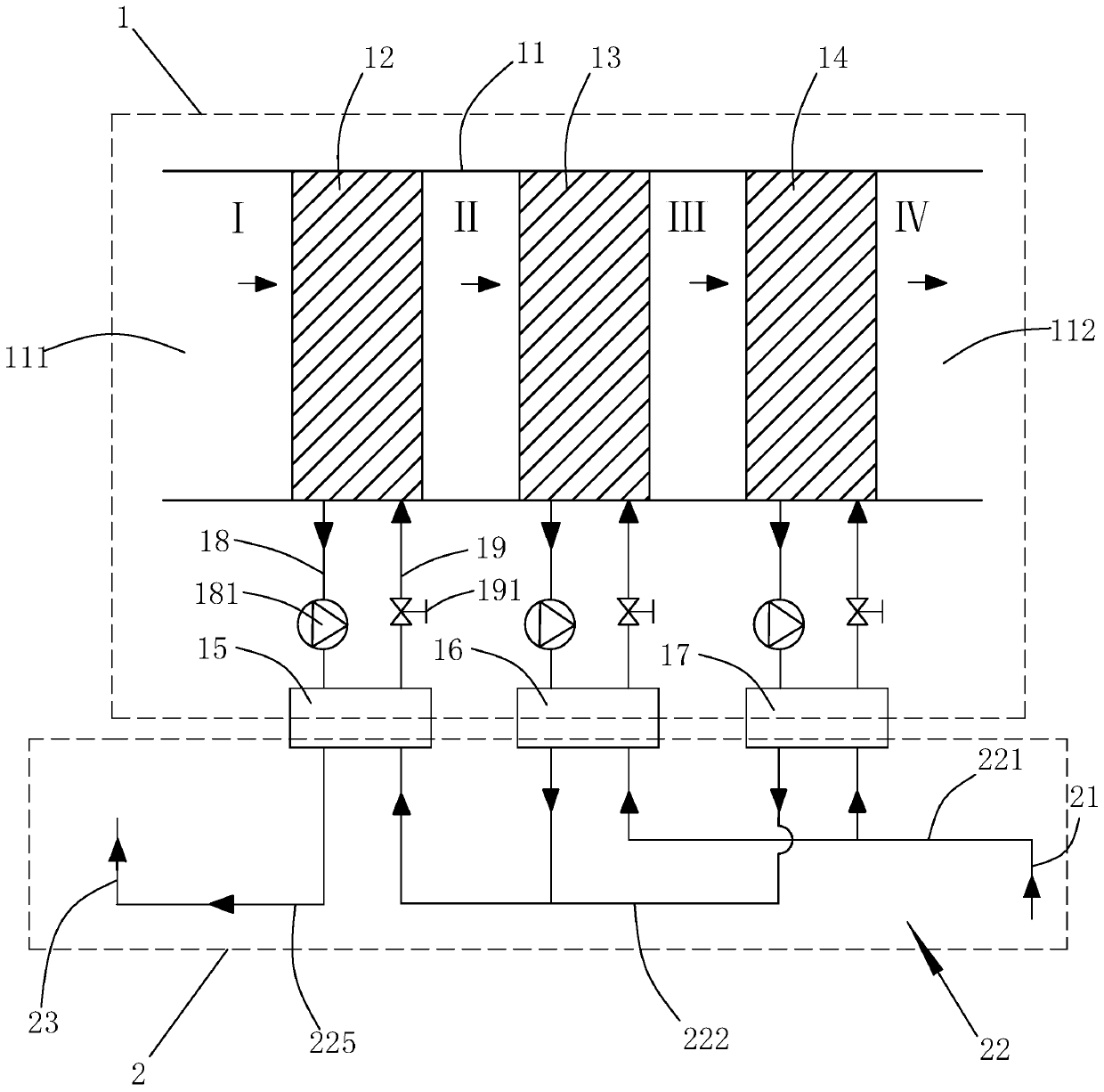
[0006] Through the above technical solution, the problem of flue gas dewhitening is solved, pollution emission is reduced, and the waste heat of flue gas is recovered and utilized; when in use, the wet flue gas discharged from the boiler enters the flue gas duct through the air inlet of the flue gas duct , and then pass through each evaporator in turn, and finally discharged from the air outlet of the flue gas duct. When the flue gas passes through each evaporator, the flue gas acts as a heat source to make the refrigerant in the corresponding evaporator absorb heat and evaporate, thereby reducing the temperature of the flue gas , so that most of the water vapor in the flue gas is liquefied into liquid water, and at the same time, the sulfur dioxide and nitrogen oxides in the flue gas will also dissolve into the liquid water, thereby realizing the filtration of sulfur dioxide and nitrogen oxides, and also realizing the removal of flue gas At the same time, under the action of the circulation loop, the high-temperature gaseous condensing agent in the evaporator enters the corresponding condenser, and liquefies in the condenser to release heat, and the heat released by the liquefaction of the condensing agent will be passed into the condensation through the waste heat recovery pipeline. The water in the device is absorbed, and finally discharged through the outlet pipe, so as to realize the heating of water and the waste heat recovery of flue gas

Method used


Image

  • System used for white flue gas removal and waste gas recycling
  • System used for white flue gas removal and waste gas recycling
  • System used for white flue gas removal and waste gas recycling

Examples


Embodiment 1

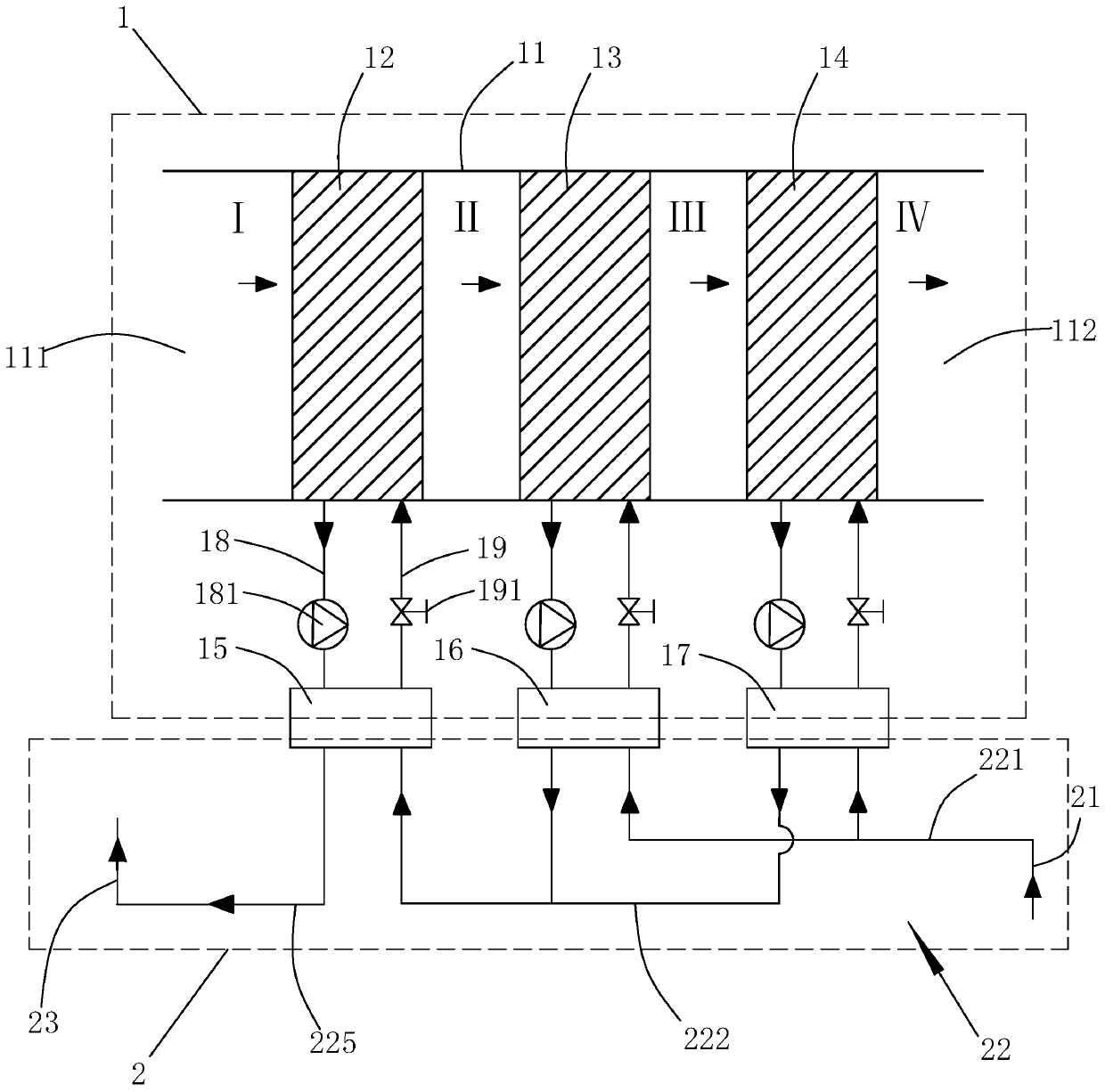
[0024] A system for flue gas dewhitening and waste heat recovery, refer to figure 1 , including a flue gas dewhitening device and a waste heat recovery device, the flue gas dewhitening device includes a flue gas duct and a water-cooled air-conditioning heat pump unit, and the air-conditioning heat pump unit is composed of at least three heat pump air conditioners.

[0025] A heat pump air conditioner includes an evaporator, a condenser, and a refrigerant circulation circuit connected between the evaporator and the condenser. The refrigerant circulation circuit includes a return air pipe connected between the refrigerant outlet of the evaporator and the refrigerant inlet of the condenser, a compressor installed on the return air pipe, an outlet pipe connected between the refrigerant outlet of the condenser and the refrigerant inlet of the evaporator The liquid pipe and the expansion valve installed on the liquid outlet pipe. When the heat pump air conditioner is working, the r...

Embodiment 2

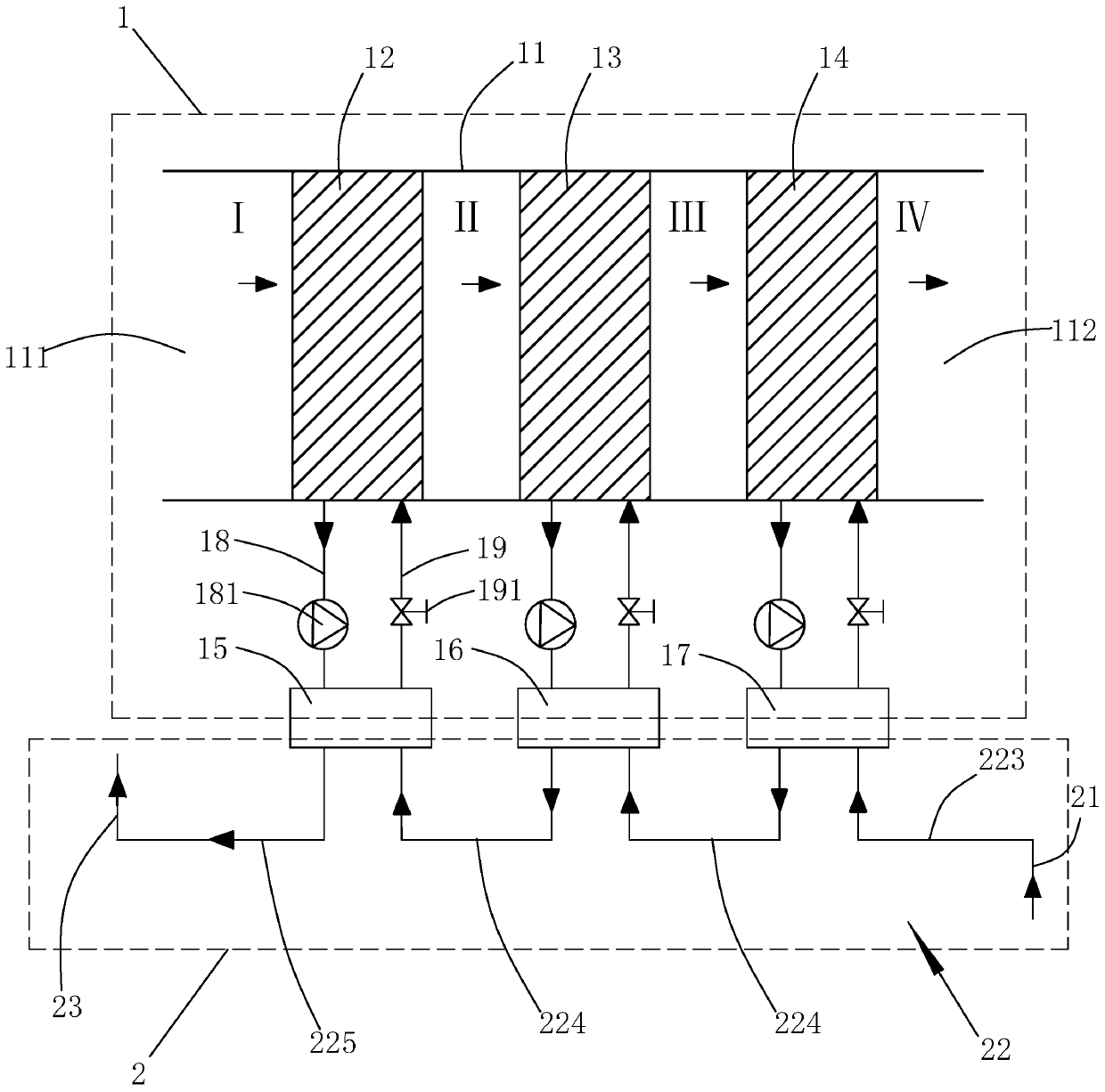
[0033] The difference between this embodiment and Embodiment 1 is that, referring to figure 2 , the waste heat recovery device includes a water inlet pipe connected and communicated with the municipal heating heating return pipe, a waste heat recovery pipeline connected to the outlet end of the water inlet pipe, and an outlet pipe connected and communicated with the municipal heating outlet pipe at the water outlet end, and the inlet pipe of the outlet pipe The water end is connected and communicated with the drain port of condenser A.

[0034] The waste heat recovery pipeline includes the water inlet connecting pipe connecting the water inlet of the C condenser and the water inlet pipe outlet, several waste heat recovery connecting pipes connecting the A condenser, each B condenser and the C condenser in series, and connecting the A condenser. The drain connection pipe between the drain outlet and the water inlet end of the outlet pipe.

[0035] When in use, municipal heati...


PUM


Abstract

The invention discloses a system used for white flue gas removal and waste gas recycling. The system comprises a white flue gas removal device and a waste heat recycling device, wherein the white fluegas removal device comprises a flue gas air flue and a water-cooling type air conditioner heat pump unit; one end of the flue gas air flue is provided with an air outlet, and the other end of the flue gas air flue is provided with an air outlet; the water-cooling type air conditioner heat pump unit comprises at least three heat pump type air conditioners; each heat pump type air conditioner comprises an evaporator arranged in the flue gas air flue, a condenser arranged outside the flue gas air flue, and a refrigerant circulating loop connected between the evaporator and the condenser, whereinthe evaporator is arranged in a spaced mode in a flue gas flowing direction; and the waste heat recycling device comprises a water inlet tube, a water outlet tube and a waste gas recycling pipeline for introducing water in the water inlet tube into each condenser and discharging water flowing out from each condenser into the water outlet tube. The system has the advantages that the white flue gasremoval is achieved, pollutant discharge is reduced, and flue gas waste heat is recycled.

Description

technical field [0001] The invention relates to the technical field of flue gas dewhitening, in particular to a system for flue gas dewhitening and waste heat recovery. Background technique [0002] Since the implementation of green energy-saving industry in my country, waste heat recovery devices will be installed in the exhaust pipes of many coal-fired, gas-fired and oil-fired boilers. There is still a lot of heat in the flue gas at 50°C-70°C that has not been effectively utilized. [0003] Moreover, sulfur dioxide, nitrogen oxides and a large amount of water vapor will be carried in the exhaust smoke of the boiler. In winter, the water vapor in the flue gas meets the cold air and condenses at the chimney outlet, forming a large amount of white smoke, which affects the surrounding residents. If the white smoke phenomenon is not controlled for a long time, it will destroy the surrounding ecological environment. Contents of the invention [0004] The object of the present...

Claims


Application Information

Patent Timeline
Patent Type & Authority Applications(China)
IPC IPC(8): F23J15/06F24F5/00
CPCF23J15/06F24F5/001Y02E20/30
Inventor 黄智强
Owner 北京德克浦智慧能源科技有限公司
Learn More