
Computing method for pollutant emission of distributed energy system

A distributed energy and calculation method technology, which is applied in the field of calculation of pollutant emissions from distributed energy systems, and can solve problems that may be gas and other fuels, which cannot be calculated in distributed energy systems, and cannot accurately reflect emission reductions. and other problems to achieve high accuracy

Inactive Publication Date: 2018-01-16
ENN ENERGY SERVICE
View PDF5 Cites 4 Cited by
  • Summary
  • Abstract
  • Description
  • Claims
  • Application Information

AI Technical Summary

Problems solved by technology

[0003] The above calculation method of the emission reduction of the distributed energy system has the following disadvantages: firstly, it is impossible to calculate the emission of the distributed energy system itself; The fuel of the system, as well as the power generation fuel of the power grid, is not necessarily coal, and may also be gas and other fuels. Therefore, there are certain problems in this calculation method, which cannot accurately reflect the actual emission reduction

Method used


Image

  • Computing method for pollutant emission of distributed energy system

Examples


Embodiment Construction

[0035] Embodiments of the present invention are described in detail below, examples of which are shown in the drawings, wherein the same or similar reference numerals designate the same or similar elements or elements having the same or similar functions throughout. The embodiments described below by referring to the figures are exemplary only for explaining the present invention and should not be construed as limiting the present invention.

[0036] In describing the present invention, it should be understood that the terms "center", "longitudinal", "transverse", "upper", "lower", "front", "rear", "left", "right", " The orientations or positional relationships indicated by "vertical", "horizontal", "top", "bottom", "inner" and "outer" are based on the orientations or positional relationships shown in the drawings, and are only for the convenience of describing the present invention and Simplified descriptions, rather than indicating or implying that the device or element refe...


PUM


Abstract

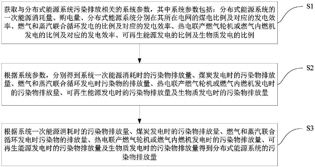
The invention provides a computing method for a pollutant emission of a distributed energy system. The method comprises the steps that system parameters relevant to the pollutant emission of the distributed energy system are acquired; according to the system parameters, a pollutant emission during primary energy consumption, a pollutant emission during coal power generation, a pollutant emission during gas and steam combined cycle power generation, a pollutant emission during power generation through a cogeneration gas turbine or a gas engine, a pollutant emission during renewable energy powergeneration and a pollutant emission during biomass power generation of the system are obtained respectively; and the pollutant emission of the distributed energy system is obtained according to the obtained pollutant emissions. Through the method, the pollutant emission of the distributed energy system can be computed scientifically and effectively, and the computing result is high in accuracy.

Description

technical field [0001] The invention relates to the field of energy technology, in particular to a method for calculating the discharge of pollutants in a distributed energy system. Background technique [0002] At present, there is no method for estimating the emissions of distributed energy systems in related fields, only the calculation method for emission reductions. The emission reduction of the distributed energy system refers to the reduction of pollutant emissions compared with the baseline system under the condition of obtaining the same power supply and heat supply. For new buildings, "power grid power supply, electric refrigerator for cooling, and gas boiler heating system" are used as the benchmark system. The calculation formula for the emission reduction of the gas-fired cooling, heating and power distributed energy system is summarized as follows: emission reduction = (primary energy consumption of the benchmark system - primary energy consumption of the dist...

Claims


Application Information

Patent Timeline
IPC IPC(8): G06F19/00
Inventor 胡子乔郭艳军
Owner ENN ENERGY SERVICE
Learn More