

New power battery pack protection board
A technology for power battery packs and protection boards, applied in secondary battery repair/maintenance, secondary batteries, secondary battery components, etc., can solve the problems of reducing mileage, energy waste, etc., to prevent performance degradation and reduce manufacturing costs The effect of low cost and easy power battery matching
- Summary
- Abstract
- Description
- Claims
- Application Information
AI Technical Summary
Problems solved by technology
Method used
Image

Examples
Embodiment 1
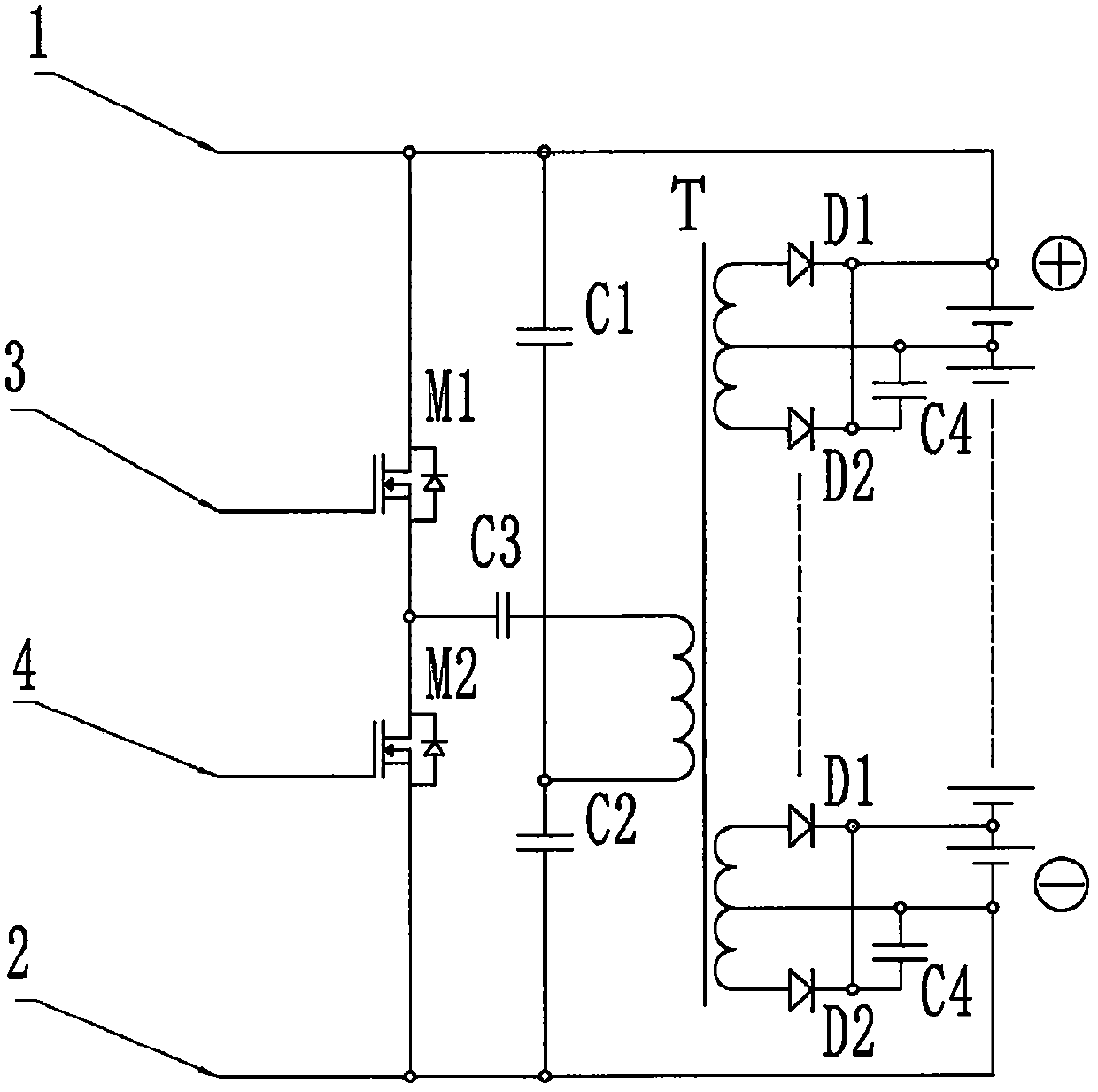
[0030] Embodiment 1: as figure 2 As shown, the half-bridge type single multi-winding isolation transformer is naturally balanced balanced charging and balanced discharge circuit 7-1, which is composed of MOS tubes M1, M2 and capacitors C1, C2, C3 + single multi-winding isolation transformer T1 + rectification Diodes D1, D2 and capacitor C4 are composed together, wherein: in the half-bridge DC-AC circuit composed of MOS transistors M1, M2, capacitors C1, C2, C3 and the primary side winding of the multi-winding isolation transformer T1, first M1 , M2, C1, and C2 are connected in series respectively, and then connected in parallel, the drain of M1 and the upper end of C1 are connected to the positive pole of the power battery unit 6, and the source of M2 and the lower end of C2 are connected to the negative pole of the power battery unit 6 ; The capacitor C3 is connected in series in the circuit of the primary side winding of the multi-winding isolation transformer T1, and its s...
Embodiment 2
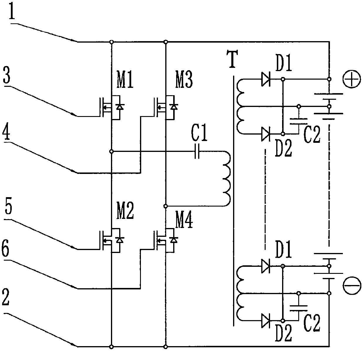
[0032] Embodiment 2: as image 3As shown, the full-bridge single multi-winding isolation transformer is naturally balanced balanced charging and balanced discharge circuit 7-2, which is composed of MOS transistors M1, M2, M3, M4 and capacitor C1+single multi-winding isolation transformer T1+ rectification Diodes D1, D2 and capacitor C2 are composed together, wherein: in the full-bridge DC-AC circuit composed of MOS transistors M1, M2, M3, M4, capacitor C1 and the primary side winding of multi-winding isolation transformer T1, first M1 , M2, M3, and M4 are connected in series respectively, and then connected together in parallel. The drains of M1 and M3 are connected to the positive pole of the power battery unit 6, and the source ends of M2 and M4 are connected to the negative pole of the power battery unit 6. ; The capacitor C1 is connected in series in the circuit of the primary side winding of the multi-winding isolation transformer T1, and its secondary side is composed of...
Embodiment 3
[0033] Embodiment 3: as Figure 4 As shown, the half-bridge N-only multi-winding isolation transformer is naturally balanced balanced charging and balanced discharging circuit 7-3, which is composed of MOS transistors M1, M2 and capacitors C1, C2, C3, C4... CN+N is composed of multi-winding isolation transformers T1, T2...TN+ rectifier diodes D1, D2 and capacitor C5, in which: MOS transistors M1, M2 and capacitors C1, C2, C3, C4 and multi-winding In the half-bridge DC-AC circuit composed of the primary side windings of isolation transformers T1 and T2, first M1, M2, C1, and C2 are connected in series respectively, and then connected in parallel. The drain of M1 and the upper end of C1 are connected to the power battery pack On the positive pole of the unit 6, the source of M2 and the lower end of C2 are connected to the negative pole of the power battery pack unit 6; the capacitors C3 and C4 are respectively connected in series in the circuits of the primary side windings of t...
PUM
 Abstract
Description
Claims
Application Information