A low thermoelastic damping cantilever microbeam resonator with through-hole structure

A technology of elastic damping and resonator, applied in the direction of impedance network, electrical components, etc., to achieve the effect of reducing energy loss and reducing thermoelastic damping

Active Publication Date: 2020-04-21
SOUTHEAST UNIV
View PDF4 Cites 0 Cited by
  • Summary
  • Abstract
  • Description
  • Claims
  • Application Information

AI Technical Summary

Problems solved by technology

However, there is currently no effective technical solution to improve the device structure

Method used


Image

  • A low thermoelastic damping cantilever microbeam resonator with through-hole structure
  • A low thermoelastic damping cantilever microbeam resonator with through-hole structure
  • A low thermoelastic damping cantilever microbeam resonator with through-hole structure

Examples


Embodiment 1

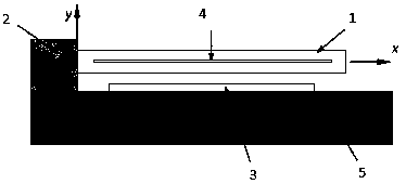
[0023] Such as figure 1 A low thermoelastic damping cantilever microbeam resonator with a through-hole structure shown, including a base 5, a driving electrode 3, a cantilever support part 2, and a suspension microbeam 1;

[0024] The driving electrodes are arranged on the upper surface of the base to excite the elastic vibration of the suspended micro-beam under the action of electrostatic force;

[0025] The cantilever support part is arranged at one end of the upper surface of the base, and is used for suspending and fixing the suspended micro-beam;

[0026] One end of the suspended micro-beam is fixed on the cantilever support part, while the suspended micro-beam is located above the driving electrode and arranged parallel to the base; figure 1 In , the length direction of the suspended microbeam is the x direction (long side direction), and the thickness direction of the suspended microbeam is the y direction. The suspended microbeam deforms along the y direction (thi...

Embodiment 2

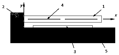
[0049] The difference with Embodiment 1 is that if there is only one rectangular through hole when used for a particularly long suspension beam, the rectangular through hole will cause the lower beam to be too long. Under the action of electrostatic force, the strength and stiffness of the lower beam will decrease. Therefore, two or more rectangular through-holes can be designed, and the rectangular through-holes are evenly arranged along the length direction of the suspension micro-beam perpendicular to the side of the base. A plurality of rectangular through holes can make multiple physical connections between the upper beam and the lower beam, which can effectively improve the strength and stiffness of the lower beam, and can simultaneously reduce the thermoelastic damping of the suspended micro-beam.

[0050] Now analyze the technical solution with a plurality of narrow and long rectangular through holes. When the beam is particularly long, if there is only one rectangular...


PUM

PropertyMeasurementUnit
thicknessaaaaaaaaaa

Abstract

The present invention belongs to the micro-electromechanical system (MEMS) field and relates to a low-thermoelastic damping cantilever micro beam resonator having through hole structures. The low-thermoelastic damping cantilever micro beam resonator comprises a base, a driving electrode, a cantilever supporting portion and a suspension micro beam; the driving electrode is arranged on the upper surface of the base; the cantilever supporting portion is arranged at one end of the upper surface of the base; one end of the suspension micro beam is fixed on the cantilever supporting portion, and atthe same time, the suspension micro beam is located above the driving electrode; the long sides of the suspension micro beam are parallel to the base; rectangular through holes are formed in a side surface where the sides of the suspension micro beam at the length direction and the sides of the suspension micro beam at the thickness direction; the rectangular through holes are located at the center of the side surface; the length of the rectangular through holes is not smaller than a length of 0.8 times of the length of the side surface; and the width of the rectangular through holes is not larger than a width of 0.1 times of the width of the side surface. The damping peak of the resonator is in high frequencies, and is not within operating frequencies.

Description

technical field [0001] The invention belongs to the field of micro-electromechanical systems (MEMS), and in particular relates to a cantilever micro-beam resonator with a through-hole structure and low thermoelastic damping. Background technique [0002] Cantilever microbeams with bending vibration are the core part of many MEMS devices, such as microbeam resonators and filters. This kind of microbeam is generally made of Si material, and usually requires a high quality factor: that is, requires a small thermoelastic damping. Thermoelastic damping (Thermoelastic damping, referred to as TED) is a very important damping of microbeam bending vibration. This damping is due to the compression and stretching of the mechanical structure under stress, resulting in a change in volume. The volume change causes heat to be generated and dissipated, that is, the vibrating mechanical energy of the micro-beam is converted into thermal energy and dissipated. [0003] For suspended microb...

Claims


Application Information

Patent Timeline
Patent Type & Authority Patents(China)
IPC IPC(8): H03H9/02H03H9/05H03H9/24
Inventor 李普周宏月
Owner SOUTHEAST UNIV
Why Eureka
Try Eureka