
Medical humidifier

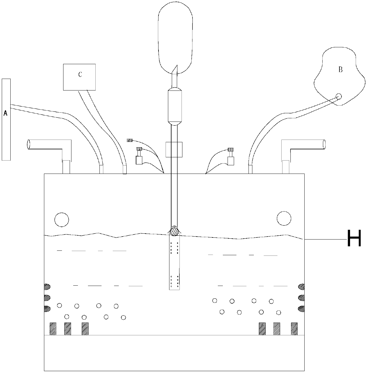
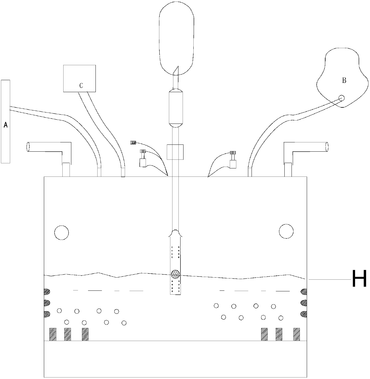
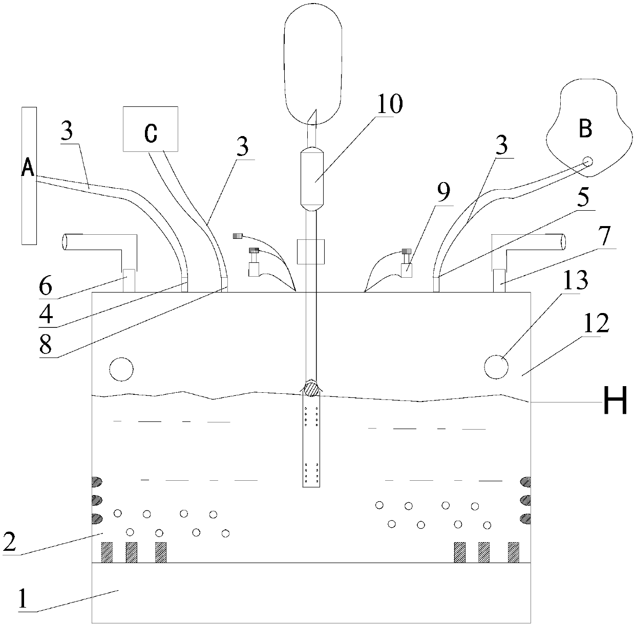
A humidifier and heater technology, applied in respirator and other directions, can solve the problems of lowering patient body temperature, high cost of humidifier, waste of resources, etc., and achieve the effect of improving thermal efficiency, improving product compatibility, and improving the degree of humidification

Pending Publication Date: 2018-01-19
毕见龙
View PDF7 Cites 5 Cited by
  • Summary
  • Abstract
  • Description
  • Claims
  • Application Information

AI Technical Summary

Problems solved by technology

3. Atomization and humidification: Atomization and humidification uses ultrasonic crystal vibration to generate very fine water mist. The commonly used humidifier is based on this principle. The temperature of the water vapor from this humidifier is close to room temperature, so it cannot be used on a ventilator for a long time. use, which could otherwise lower the patient's body temperature, this type of humidifier also has technical drawbacks
[0005] However, for the closest prior art, it mainly involves the second type (that is, the humidifier of heating and humidification mode), the heating efficiency of the heater of the humidifier is low, and it takes a long time to produce humidified gas. At the same time, the humidification effect cannot be well adjusted (that is, the temperature control method is poor);
[0006] At the same time, the structure of the internal water storage tank of the traditional humidifier is just a simple cylinder, with four connecting pipes installed on it that cannot be disassembled and replaced, and its additional functions are more simple
That is, the existing humidifiers can only be applied to ventilators alone (or can only be applied to ordinary nose oxygen inhalation / mask oxygen inhalation patients), resulting in a great waste of resources; in the prior art, this humidifier, The humidification effect is low, and the nasal mucosa is dry and bleeding easily, resulting in dryness of the entire respiratory tract, and even chest tightness and discomfort. The cost of a humidifier with a good humidification effect is relatively high, which is not conducive to clinical use; The effect is also less, and the universal compatibility is also worse

Method used


Image

  • Medical humidifier
  • Medical humidifier
  • Medical humidifier

Examples


Embodiment Construction

[0055] The technical solutions of the present invention will be clearly and completely described below in conjunction with the accompanying drawings. Apparently, the described embodiments are some of the embodiments of the present invention, but not all of them. Based on the embodiments of the present invention, all other embodiments obtained by persons of ordinary skill in the art without making creative efforts belong to the protection scope of the present invention.

[0056] In the description of the present invention, it should be noted that the terms "center", "upper", "lower", "left", "right", "vertical", "horizontal", "inner", "outer" etc. The indicated orientation or positional relationship is based on the orientation or positional relationship shown in the drawings, and is only for the convenience of describing the present invention and simplifying the description, rather than indicating or implying that the referred device or element must have a specific orientation, ...


PUM


Abstract

The invention discloses a medical humidifier. The medical humidifier comprises a heater, a water storage tank, a plurality of connection ports and a plurality of connection pipes. Each connection portis provided with an adapter substitute. A liquid supplying machine is arranged at the top of the water storage tank. The heater comprises a heater body and cooling fins. Each cooling fin is in an S shape. A separation plate perpendicular to the bottom of the water storage tank is further arranged in the water storage tank, and the separation plate is in an S shape. Air vents are formed in the twoends of the top of the separation plate. The directions of the openings of the air vents in the two ends are used for jointly guiding the air flow flowing out in the air outlet direction to form a clockwise cyclone or an anticlockwise cyclone in the water storage tank. The medical humidifier has the technical advantages that the multiple connection ports can be compatibly used, the compatibilityof the medical humidifier is higher, the humidifying efficiency is high, and the humidifying effect is obvious.

Description

technical field [0001] The invention relates to the technical field of medical equipment, in particular to a medical humidifier. Background technique [0002] As we all know, a humidifier is a device used in conjunction with a ventilator. Its function is to heat and humidify the air flow. The wet air flow is heated and humidified by passing through the surface of the hot water, and finally exhaled through the ventilator to supply the patient with humidified gas for inhalation. [0003] At the same time, there are three main humidification methods of traditional humidifiers: 1. Cold water humidification; 2. Heating humidification; 3. Ultrasonic humidification. [0004] 1. Cold water humidification: Cold water humidification refers to the inhalation of gas directly through a container with water without heating the water to achieve the purpose of humidification at room temperature. The relative humidity of this humidifier is limited by the contact area between air and water a...

Claims


Application Information

Patent Timeline
IPC IPC(8): A61M16/16
Inventor 毕见龙封喜翠
Owner 毕见龙
Learn More