Granulating chamber of biological particle fuel extruding machine

A technology of biological pellets and extruders, applied in the direction of biofuels, waste fuels, fuels, etc., can solve the problems of raw material quality impact, heat can not be exported in time, and shorten the service life of the cylinder die, so as to reduce the quality impact and increase the use The effect of longevity

Active Publication Date: 2018-01-19
遵义双河生物燃料科技有限公司
View PDF9 Cites 5 Cited by
  • Summary
  • Abstract
  • Description
  • Claims
  • Application Information

AI Technical Summary

Problems solved by technology

[0004] The following technical problems exist in the prior art: because a large amount of frictional heat will be generated between the raw material and the die wall of the cylindrical die, and a large amount of frictional heat will also be generated when the raw material is pressed into the pelletizing hole, the heat generated on the cylindrical die wall cannot be timely Export, heat not only affects the quality of raw materials inside the cylinder mold, but also shortens the service life of the cylinder mold for a long time

Method used


Image

  • Granulating chamber of biological particle fuel extruding machine
  • Granulating chamber of biological particle fuel extruding machine
  • Granulating chamber of biological particle fuel extruding machine

Examples


Embodiment 1

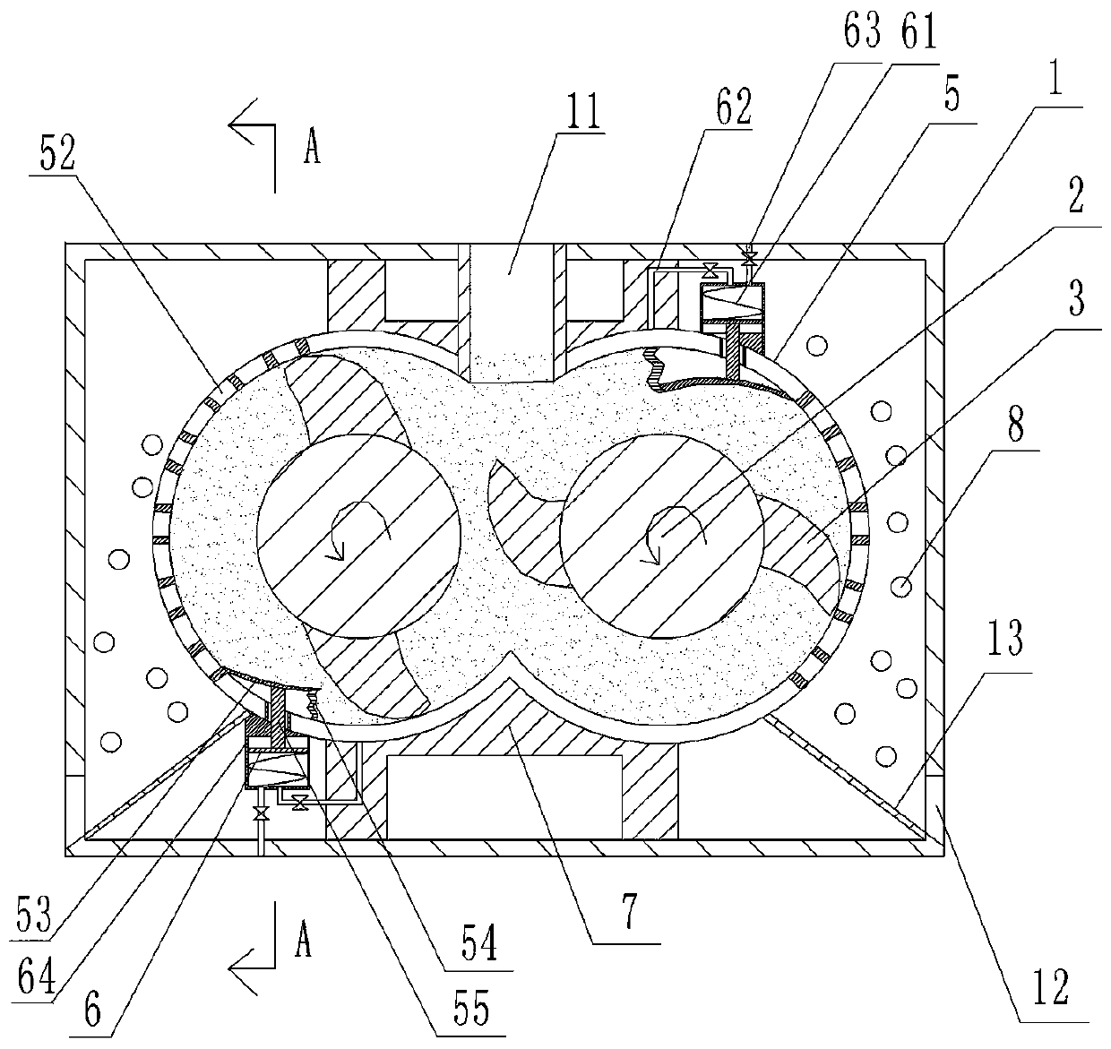
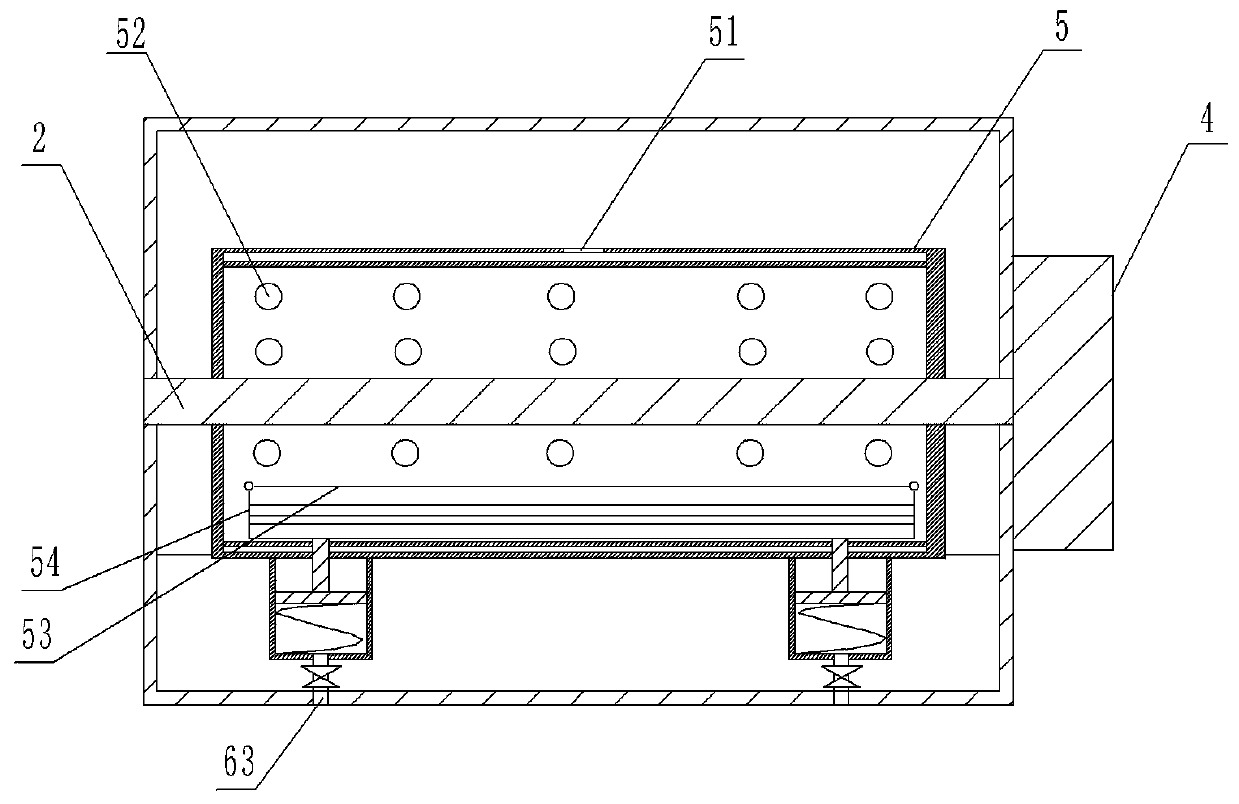
[0028] Such as figure 1 , figure 2 and image 3 As shown, the granulation chamber of the biological particle 8 fuel extruder includes a granulation chamber body 1, a rotating shaft 2, a stirring and extruding blade 3, a cylindrical mold 5 for charging and a power device for driving the rotating shaft 2; The cylinder mold 5 is located in the granulation chamber body 1, and the inside of the cylinder mold 5 is a cavity for placing raw materials. The upper part of the granulation chamber body 1 is provided with a feed pipe 11 communicating with the inner cavity of the cylindrical mold 5; the bottom of the granulation chamber body 1 is used for a discharge port 12 for discharging.

[0029] The cylinder mold 5 is composed of two symmetrically arranged C-shaped cylinders, and the two C-shaped cylinders are connected to each other; the two C-shaped cylinders in this program are respectively a left C-shaped cylinder and a right C-shaped cylinder. There are two rotating shafts 2, a...

Embodiment 2

[0040] The difference between this embodiment and Embodiment 1 is that the end of the stirring and extruding blade is slidably connected with the inner wall of the cylindrical mold, that is, when the rotating shaft drives the stirring and extruding blade to rotate, the end of the stirring and extruding blade can move along the circle. The inner wall of the barrel mold slides.

[0041] When in use, put the raw material into the cylindrical mold 5 from the feeding pipe 11, start the motor 4, and the motor 4 drives the rotating shaft 2 to rotate, (note: since there are two rotating shafts 2 in this scheme, in order to prevent the two rotating shafts from The stirring and extruding blades 3 on the 2 interfere with each other, and the left rotating shaft 2 can rotate earlier than the right rotating shaft 2, and then start the right rotating shaft 2).

[0042] The rotating shaft 2 drives the stirring and extruding blade 3 to rotate to stir and extrude the raw material in the cylindr...


PUM


Abstract

The invention relates to the technical field of extruding and granulating and especially relates to a granulating chamber of a biological particle fuel extruding machine. The granulating camber comprises a granulating chamber body, a rotating shaft, a stirring and extruding blade, a cylinder mould and a power device, wherein the cylinder mould is arranged in the granulating chamber body, a feedingpipe and a discharging opening are arranged on the granulating chamber body, the rotating shaft is arranged in the cylinder mould, the stirring and extruding blade is arranged in the peripheral direction of the rotating shaft, a cavity is formed in a mould wall of the cylinder mould, an air outlet is formed in an outer wall of the cylinder mould, a plurality of granulating pipes are arranged on the mould wall of the cylinder mould, an air blowing device is arranged in the granulating chamber body, a swinging plate is hinged to an inner wall of the cylinder mould, the stirring and extruding blade can extrude the swinging plate intermittently, an elastic cover is arranged between the inner wall, close to the swinging plate, of the cylinder mould and the swinging plate, a push portion is connected to the swinging plate, and the upper end of the push portion is arranged in the elastic cover. By means of the scheme, heat generated by the walls of the cylinder mould is reduced, further an effect on quality of a raw material in the cylinder mould is reduced, and meanwhile service life of the cylinder mould is prolonged.

Description

technical field [0001] The invention relates to the technical field of extrusion granulation, in particular to a granulation chamber of a biological particle fuel extruder. Background technique [0002] Extrusion granulation is to prepare the soft material from the raw powder with an appropriate binder, put it into a porous ring die (usually an orifice or a screen with sieve holes), and use forced extrusion to make it from the porous ring die. The other side is discharged, and then undergoes appropriate granulation or shaping granulation method. At present, the extruder is mainly composed of a main motor, a reducer, a granulation chamber, a dust cover, and a dial motor. The granulation chamber is the core part of the extruder. For compact particles. [0003] The traditional extruder granulation is divided into front extrusion type and side extrusion type; the granulation chamber of the front extrusion type includes a helical blade driven by a motor, a rotating shaft, a cyl...

Claims


Application Information

Patent Timeline
Patent Type & Authority Applications(China)
IPC IPC(8): B01J2/22C10L5/44
CPCY02E50/10Y02E50/30
Inventor 刘福基
Owner 遵义双河生物燃料科技有限公司
Why Eureka
Try Eureka