

Rotary part drilling method and drilling clamp
A technology of rotary parts and drilling jigs, which is applied in the direction of drilling molds for workpieces, metal processing machinery parts, manufacturing tools, etc., can solve the problems of difficult to ensure relative positional relationship, increase processing costs, and reduce labor production efficiency. Achieve high industrial practical value, improve efficiency, and simple structure
- Summary
- Abstract
- Description
- Claims
- Application Information
AI Technical Summary
Problems solved by technology
Method used
Image

Examples
Embodiment Construction
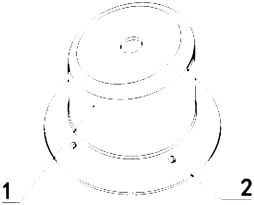
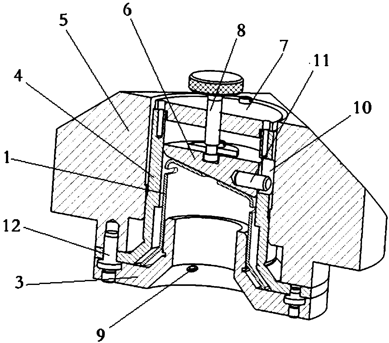
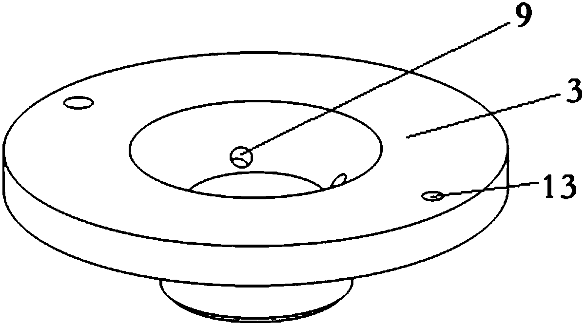
[0014] Referring to the accompanying drawings, the application is aimed at the rotary parts such as figure 1 As shown, a plurality of normal holes 2 in different directions need to be processed on the bell mouth wall of the rotary part 1. In order to improve the drilling efficiency of multiple normal holes in the rotary part, the drilling jig provided by this application contains a drilling template 3. Drilling template base 5, sleeve 4, profile slider 6, the said drilling template 3 is a funnel shape with a pressure edge, and the funnel wall of the drilling template 3 is provided with a normal hole 2 for the rotary parts Matching jig hole 9, the center of the jig base 5 has a central hole 15 matching the sleeve 4, and the upper surface of the jig base 5 has a protruding connection platform matching the edge of the jig template, and the connection platform is provided with There are connecting holes, the lower surface of the jig base 5 is a polyhedron 14 matched with the rotar...
PUM
 Abstract
Description
Claims
Application Information