
Discharge roller of a stretching machine

A technology of discharge roller and stretching machine, which is applied in the direction of rolling out thin soft materials, thin material handling, transportation and packaging, etc. It can solve problems such as wrinkles and uneven cloth, and improve the ability to recover from deformation, which is not easy The effect of slipping and increasing the axial force component

Inactive Publication Date: 2019-05-07
北京快鹿织造有限公司
View PDF12 Cites 0 Cited by
  • Summary
  • Abstract
  • Description
  • Claims
  • Application Information

AI Technical Summary

Problems solved by technology

[0004] Generally, the texture of the fabric is relatively soft. In this solution, the fabric may be wrinkled during the process of flattening from the main output roller on the workbench, resulting in the unevenness of the fabric stacked on the workbench.

Method used


Image

  • Discharge roller of a stretching machine
  • Discharge roller of a stretching machine
  • Discharge roller of a stretching machine

Examples


Embodiment

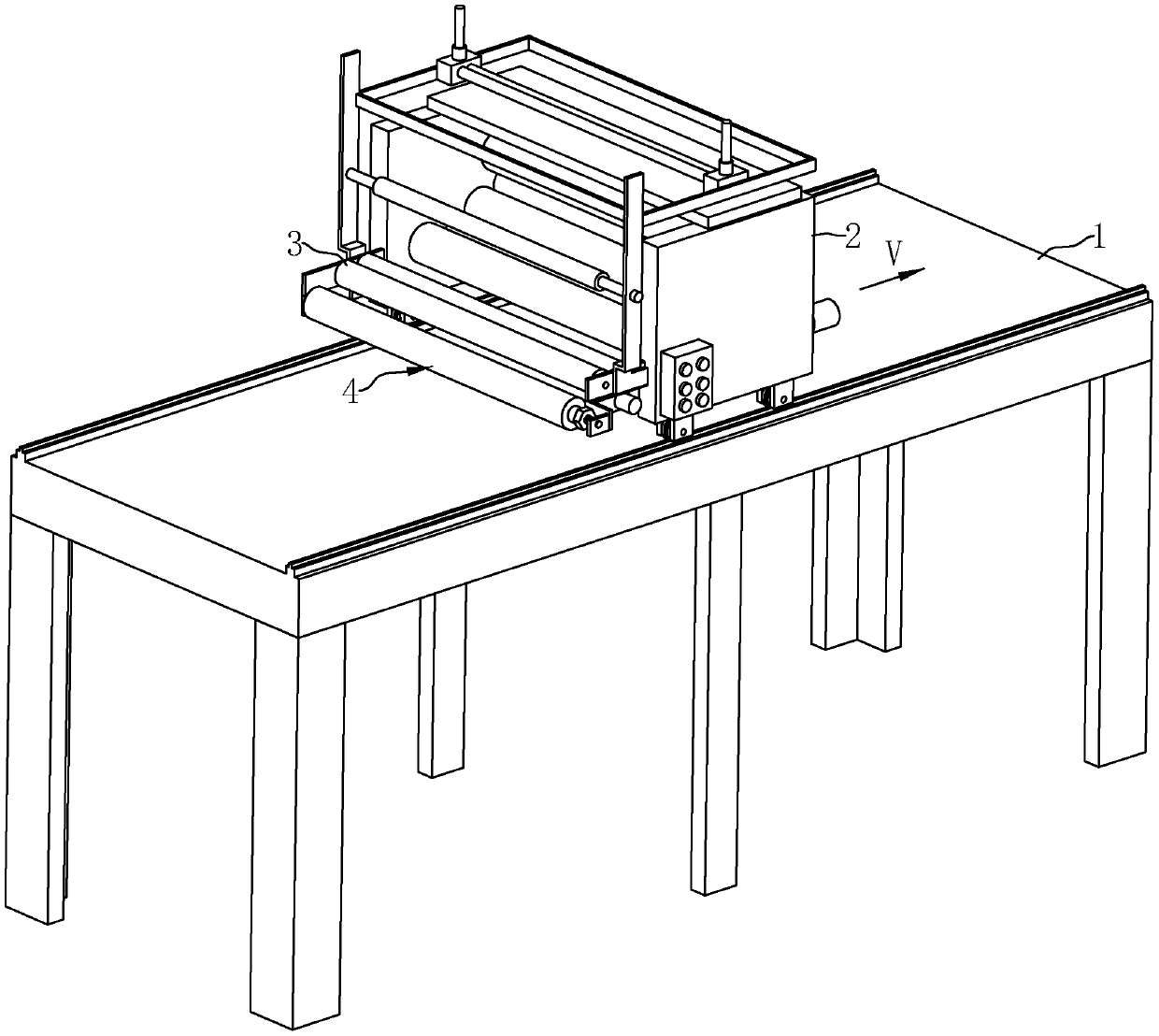
[0039] Embodiment: a kind of discharging roller of spreading machine, as figure 1 As shown, the stretching machine includes a workbench 1 and a moving frame 2 that can move horizontally and linearly on the workbench 1. The moving frame 2 is divided into a feed end and a discharge end. The feed end is located at figure 1 One end in the direction indicated by the middle arrow V, the discharge end is located at the other end of the moving frame 2 opposite to the feed end, and the moving frame 2 is rotatably connected to a pair of main output rollers 3 arranged side by side close together at the discharge end for Output the cloth to the top of the workbench 1 smoothly; the cloth roll enters the moving frame 2 from the feeding end, passes through the discharging end, and then goes around the main output roller 3, and the moving frame 2 moves along the figure 1 When moving in the direction indicated by the middle arrow V, the cloth passes out from under the main output roller 3 and ...


PUM


Abstract

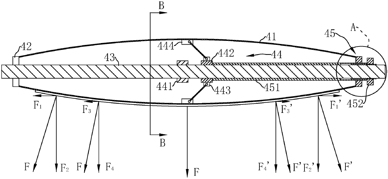
The invention discloses a discharging roller of a spreading machine. The discharging roller comprises a cylinder for cloth winding and a rotation shaft rotationally connected with the cylinder, and the middle of the cylinder outwards protrudes and is in an arc shape. The discharging roller further comprises an expanding mechanism which is arranged in the cylinder and used for expanding the cylinder so as to reduce the curvature radius of the outer surface of the cylinder. The expanding mechanism comprises a sliding sleeve which is in sliding cup joint to the rotation shaft, and supporting rodsare hinged to the part between the sliding sleeve and the inner wall of the cylinder. The discharging roller further comprises a nut which is in threaded connection to the rotation shaft, and an ejector pipe which is in sliding cup joint to the part between the nut and the sliding sleeve. The two ends of the ejector pipe abut against the sliding sleeve and the nut correspondingly. The ends, awayfrom the sliding sleeve, of the supporting rods face the end, away from the ejector pipe, of the rotation shaft. The ends, away from the sliding sleeve, of the supporting rods incline in the directionaway from the rotation shaft. The discharging roller further comprises a fixing sleeve which is fixedly in cup joint to the rotation shaft and is used for abutting against the sliding sleeve after the sliding sleeve slides so as to prevent the supporting rod inclination direction from changing. The discharging roller further comprises an elastic rod embedded in the cylinder in the center axis direction of the cylinder, and the outer surface of the cylinder is wrapped by a soft rubber layer.

Description

technical field [0001] The invention relates to a spreading machine, in particular to a discharge roller of the spreading machine. Background technique [0002] The stretching machine is used to unfold the cloth on the cloth roll and fold it flat together, which is convenient for plate making or other processing. [0003] For example, the Chinese patent application document whose publication number is CN103144998A discloses a spreading machine. It includes a working table and a moving frame that can move horizontally along the length of the working table. One end of the moving frame is the feeding end of the cloth, and the other end is the discharging end of the cloth. The cloth roll enters the moving frame from the feeding end, and the discharging end is set There are two main output rollers that are close in parallel and are used to support the cloth roll. The moving frame moves along the working table, and the cloth passes through the main output rollers and is flattened...

Claims


Application Information

Patent Timeline
Patent Type & Authority Patents(China)
IPC IPC(8): B65H47/00
Inventor 果辉
Owner 北京快鹿织造有限公司
Learn More