Rinsing tank used in tailing regeneration treatment of regeneration papermaking

A treatment process and rinsing tank technology, applied in the field of rinsing tanks, can solve the problems of separation of unfavorable impurities, inability to fully disperse feeding parts, inability to fully expose and separate impurities, etc.

Active Publication Date: 2016-10-26
广东致顺化工环保设备有限公司
View PDF9 Cites 3 Cited by
  • Summary
  • Abstract
  • Description
  • Claims
  • Application Information

AI Technical Summary

Problems solved by technology

[0005] 1. When the recycled materials are stirred by the stirring device, since the stirring device works to disperse and stir the materials in the circumferential direction of the rotating shaft, there is no material transfer in the axial direction (the width direction of the tank body) , and the material to be processed is generally fed at a fixed point when feeding. On the one hand, the dispersed material cannot be evenly distributed in the axial direction of the rotating shaft; on the other hand, the feeding part cannot be fully dispersed due to excessive material accumulation. Because the materials to be treated cannot be fully and evenly spread, the materials cannot be fully separated and the impurities cannot be fully exposed and separated, thus affecting the cleaning effect and efficiency
[0006] 2. The existing commonly used stirring device has poor separation effect on pulp an...

Method used


Image

  • Rinsing tank used in tailing regeneration treatment of regeneration papermaking
  • Rinsing tank used in tailing regeneration treatment of regeneration papermaking
  • Rinsing tank used in tailing regeneration treatment of regeneration papermaking

Examples


Embodiment 1

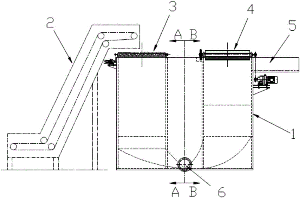
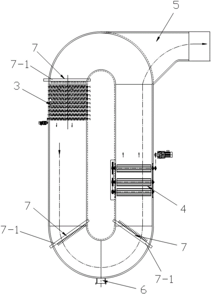
[0048] see Figure 1-Figure 4 , The rinsing tank in the recycling process of recycled papermaking tailings in this embodiment is mainly composed of a tank body 1 and a breaking device 3 provided on the tank body 1 , a shear separation cleaning device 4 and a material booster device 7 . in:

[0049] see Figure 1-Figure 4 , the tank body 1 has an annular structure, and an annular flow channel is formed inside; the bottom of the tank body 1 is provided with a sediment discharge port 6 , and the top is provided with a floating material discharge port 5 .

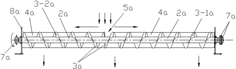
[0050] see Figure 1-Figure 4 , Figure 6-Figure 8 , the dispersing device 3 is arranged at the feeding position in the tank body 1, the dispersing device 3 includes a plurality of dispersing units 1a arranged together, and each dispersing unit 1a includes a dispersing rotating shaft 2a, which is located at the dispersing unit 1a The helical blade 3a on the rotating shaft 2a and the tearing part 4a arranged on the rotating sha...

Embodiment 2

[0069] The difference between this embodiment and the embodiment is that in this embodiment:

[0070] see Figure 14 , in the dispersing device 3, the dispersing unit 1a is arranged in a multi-layer structure in the vertical direction; a plurality of dispersing units 1a in each layer of dispersing units 1a are arranged in parallel on the same level; Wherein, the lower part of the uppermost layer of dispersing units 1a is immersed in the cleaning solution 11a, and the rest of the dispersing units 1a are immersed in the cleaning solution 11a. Figure 14Only two floors are shown in the figure, from top to bottom are the first floor dispersal unit 1-1a and the second floor dispersal unit 1-2a. In the dispersing unit 1a of the same layer above, the former dispersing unit 1a disperses the material 10a while forwarding it, and the latter dispersing unit 1a takes over the transported material 10a and continues to disperse it and convey it forward. After a plurality of breaking-up un...

Embodiment 3

[0074] The difference between this embodiment and the embodiment is that in this embodiment:

[0075] see Figure 16 with Figure 17 , in the dispersing device 3, in the dispersing unit 1a on the same floor, the left-handed blades 3-1a and the right-handed blades 3-2a in two adjacent dispersing units 1a are respectively arranged on different sides of the dispersing shaft 2a. End, that is: when the left-handed blade 3-1a (or right-handed blade 3-2a) in the first dispersing unit 1a is set at the left end (or right end) of the dispersing shaft 2a, the second adjacent The left-handed blades 3-1a (or right-handed blades 3-2a) of each dispersing unit 1a are arranged at the right end (or left end) of the dispersing shaft 2a; and all the dispersing shafts 2a turn in the same direction. The advantage of adopting this arrangement is that since the left-handed blades 3-1a and the right-handed blades 3-2a in two adjacent dispersing units 1a are respectively arranged at different ends of...


PUM


Abstract

The invention discloses a rinsing tank used in tailing regeneration treatment of regeneration papermaking. The rinsing tank includes a tank body, a dispersing device, and a cutting separating cleaning device. The dispersing device includes a plurality of dispersing units which are arranged together, and each dispersing unit includes a dispersing rotation shaft, a screw blade arranged on the dispersing rotation shaft, and a tearing piece arranged on the dispersing rotation shaft; and the screw blade consists of a left blade and a right blade which are arranged at two ends of the dispersing rotation shaft. The cutting separating cleaning device includes a plurality of cutting cleaning mechanisms, and each cutting cleaning mechanism includes a cleaning rotation shaft and a cutting blade; and the liner velocity of the cutting blade of the posterior cutting cleaning mechanism is greater than the linear velocity of the cutting blade of the previous cutting cleaning mechanism in the flowing direction of cleaning liquid. The rinsing tank can allow a material to be treated to be fully dispersed and evenly spread, allow impurities to be fully exposed and separated, can improve the cleaning efficiency and effect, and can improve the separating efficiency between paper pulp and plastic.

Description

technical field [0001] The invention relates to recycling and processing equipment for renewable resources, in particular to a rinsing tank in the recycling process of recycled papermaking tailings. Background technique [0002] Recycled papermaking is a papermaking process based on waste paper, which can realize the reuse of waste paper resources, save energy and protect the environment. The tailings produced in the recycled papermaking process contain plastics, paper pulp, wood chips, textiles, metals, soil, sand and other impurities. Recycling these tailings can not only avoid environmental pollution, but also achieve full recovery of resources. The recyclable materials in the tailings are mainly plastics, pulp and metals, and these recyclable materials need to be fully separated during the tailings regeneration process. [0003] In the existing recycled papermaking tailings recycling process, the separation of pulp, plastics (including submerged materials and floating m...

Claims


Application Information

Patent Timeline
IPC IPC(8): D21B1/32D21B1/34D21C9/02
CPCD21B1/32D21B1/347D21C9/02Y02W30/64
Inventor 冯愚斌
Owner 广东致顺化工环保设备有限公司
Why Eureka
Try Eureka