Melt electrostatic spinning device

A spinning device, fusion electrostatic technology, applied in textiles and papermaking, filament/thread forming, fiber processing, etc., can solve the problems of spinning properties, impact, time and cost consumption, etc.

Inactive Publication Date: 2018-01-19
TONGXIANG YIZHIJIANNENG INFORMATION TECH
View PDF10 Cites 5 Cited by
  • Summary
  • Abstract
  • Description
  • Claims
  • Application Information

AI Technical Summary

Problems solved by technology

[0007] Since the molten high-temperature polymer melt needs to be transferred and flowed in the spinning assembly, it is inevitable that the high-temperature melt will be in contact with the spinning assembly, and it will inevitably be on the surface of the spinning assembly. There is adhesion. Although the surface of the spinning component can be processed smooth enough at present, the adhesion of polymers caused by surface problems has been greatly reduced. However, due to the processing accuracy and processing technology However, it is difficult to make the surface completely smooth, so that the adhesion of the polymer will still occur; in the prior art, there is also a solution of adding a lubricant between the polymer and the surface of the spinning component during the spinning process, so that It will have a certain anti-adhesion effect, but these added lubricants will inevitably enter the polymer, and then the properties of the polymer and the properties of subsequent spinning will have unpredictable effects, and it is not advisable
Due to the adhesion of the polymer during the spinning process, it is necessary to thoroughly clean the spinning group after the production plan of a batch is not completed. The cleaning of the spinning group will lead to a great consumption of time and cost, and There will still be some dead corners that are difficult to clean, which will adversely affect subsequent production

Method used


Image

  • Melt electrostatic spinning device

Examples


Embodiment 1

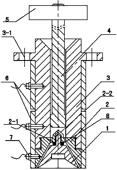
[0046] The spinning device mainly includes a spinning nozzle 1, a spinning nozzle kit 2, a nozzle sleeve 3, a plunger 4, a counterweight plate 5, a heating device 6, a temperature sensor 7, and an elastic sealing ring 8. The spinning nozzle 1 and the spinning nozzle kit 2 and the upper part of the nozzle kit 2 and the nozzle sleeve 3 are all connected by threads, and can be automatically centered through concentricity during installation. The plunger 4 is placed inside the nozzle sleeve 3, Its upper end is connected with the counterweight plate 5 through threads to apply pressure to the melt in the sleeve. The nozzle sleeve 3 is fixed on the spinning frame through uniformly distributed bolt holes 3-1, and the heating device 6 is placed on the nozzle. The periphery of the sleeve 3 can be easily disassembled, the temperature sensor 7 is placed inside the nozzle sleeve, the heating device 6 is connected with the temperature sensor 7 and the temperature control box, and the elastic...


PUM

PropertyMeasurementUnit
surface areaaaaaaaaaaa
diameteraaaaaaaaaa

Abstract

A melt electrostatic spinning device comprises a spinning nozzle, a spinning nozzle suite, a nozzle sleeve, a plunger, a counterweight disk, a heating device, a temperature sensor and an elastic sealing ring. Concave-convex anti-adhesion structures are arranged on the surfaces of all parts, making contact with a molten polymer, of a melt electrostatic spinning assembly so that the anti-adhesion effect of polymer melt in the spinning assembly can be achieved. According to the action mechanism of the concave-convex anti-adhesion structures, the concave-convex anti-adhesion structures comprise concave parts and convex parts, the convex parts are higher than the surfaces of the parts, and the direct contact between the high-viscosity polymer melt and the surfaces of the parts is reduced by utilizing the supporting action between points; besides, a gas suspension effect is formed under the action of the high-temperature high-pressure melt, and self-separation type adhesion prevention is achieved.

Description

technical field [0001] The invention relates to the technical field of textiles, in particular to a melt electrostatic spinning device. Background technique [0002] The earliest record of the melt spinning process comes from a British patent in 1845. In 1939, melt spinning was industrialized as a production process for the manufacture of nylon 66 fibers. The basic process of melt spinning includes material melting, extrusion from the micropores of the spinneret, and cooling and solidification of the melt stream. The finished filament can be wound into a bobbin or otherwise processed. In the process of melt spinning, the polymer is fed into the extruder, conveyed by the screw, plasticized, melted and then forwarded to the metering accumulator: the metering polymer ensures that the melt of the polymer can flow stably and evenly into the In the spinning assembly of the key component, the melt in the spinning assembly is filtered by the filter medium to remove impurities and...

Claims


Application Information

Patent Timeline
Patent Type & Authority Applications(China)
IPC IPC(8): D01D5/00
Inventor 朱龙泉
Owner TONGXIANG YIZHIJIANNENG INFORMATION TECH
Why Eureka
Try Eureka