
Coiled tubing directional tool control system and method for micro wellbore

A control system and micro-hole technology, applied in the automatic control system of drilling, directional drilling, earthwork drilling and mining, etc., can solve the problems of occupying the rock-carrying mud channel, unreliable locking mechanism, and unsuitable directional tools, etc., to achieve The effect of saving design space, convenient control, and saving operation auxiliary time

Active Publication Date: 2020-08-04
SOUTHWEST PETROLEUM UNIV
View PDF6 Cites 0 Cited by
  • Summary
  • Abstract
  • Description
  • Claims
  • Application Information

AI Technical Summary

Problems solved by technology

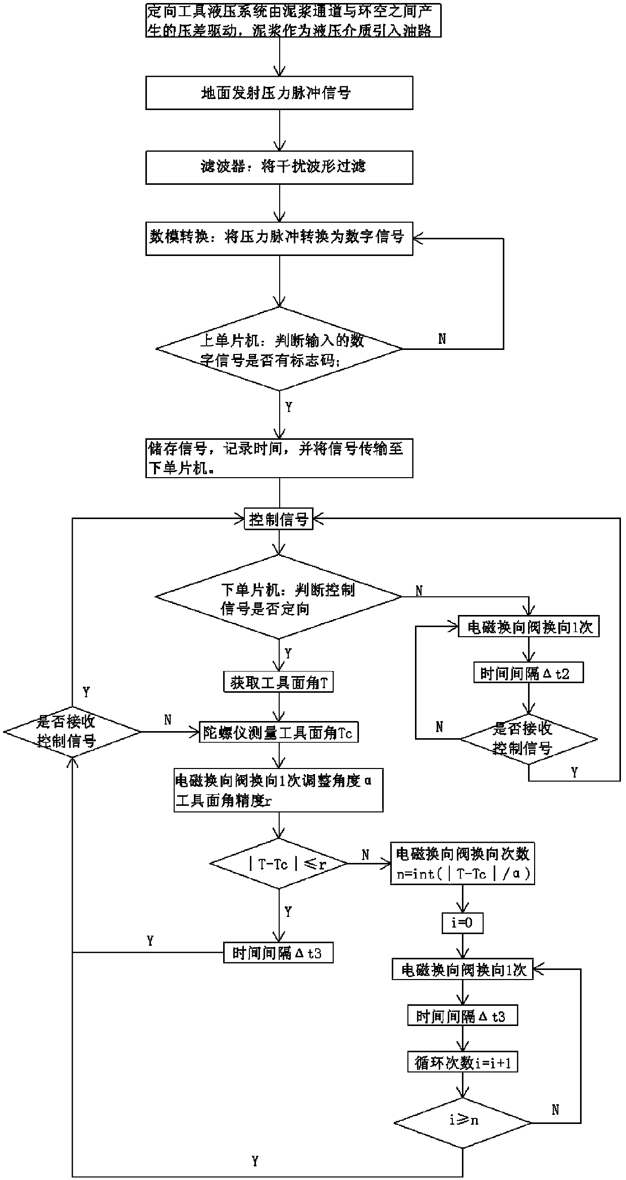
[0004] The invention overcomes the defects of the existing electro-hydraulic or pure electric driven coiled tubing directional tools, that is, external cables are required, and the rock-carrying mud channel is occupied during the drilling process of the micro-hole coiled tubing, which affects the rock-carrying effect; Greatly increased, conventional directional tools are not suitable for micro-hole drilling, and the motor is prone to heat up and cause motor failure; and the existing pure liquid coiled tubing directional tools have disadvantages such as long auxiliary operation time and unreliable locking mechanism, etc. Coiled tubing directional tool control system and method for realizing remote wireless control of directional tools, dual hydraulic cylinder drive, and mud as a power source

Method used


Image

  • Coiled tubing directional tool control system and method for micro wellbore
  • Coiled tubing directional tool control system and method for micro wellbore

Examples


Embodiment Construction

[0022] The present invention will be further described below in conjunction with accompanying drawing, protection scope of the present invention is not limited to the following:

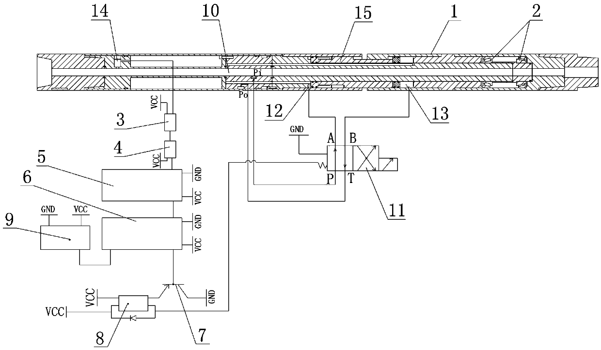
[0023] Such as figure 2 As shown in Fig. 1, a control system for the directional tool of the coiled tubing in micro wellbore, the rotating outer cylinder 1 of the directional tool is installed on the main body through the tapered roller bearing 2, and the tapered roller bearing at the left end can offset the commutation or the continuous down The tapered roller bearing at the right end can offset the axial load generated during drilling, and can transmit the counter torque generated by the bottom power drilling tool to the angle adjustment cylinder 15 at the same time. The control system includes a hydraulic circuit and a control circuit, and the control circuit includes a pressure sensor 3, a filter 4, an upper single-chip microcomputer 5, a lower single-chip microcomputer 6, a triode 7 and a relay...


PUM


Abstract

The invention discloses a control system for a micro borehole coiled tubing orienting tool. A rotation outer barrel (1) of the orienting tool is rotatably arranged on a main body through tapered roller bearings (2); the control system includes a hydraulic loop and a control loop; the control loop includes a pressure sensor (3), a filter (4), an upper single chip microcomputer (5), a lower single chip microcomputer (6), a triode (7), and a relay (8) which are successively connected; the lower single chip microcomputer (6) is connected to a gyroscope (9); a sensing probe of the pressure sensor (3) stretches to a mud channel (10) of the orienting tool; the hydraulic loop includes a two-position four-way reversing valve (11); and a solenoid valve of the two-position four-way reversing valve (11) is electrically connected to an output end of the relay (8). The invention also discloses a control method for the micro borehole coiled tubing orienting tool. The beneficial effects of the invention are that the control system and method can achieve remote wireless control of the orienting tool, can achieve dual hydraulic drive, uses mud as a power source, and can greatly save energy.

Description

technical field [0001] The invention relates to the field of coiled tubing drilling directional tools, in particular to a control system and method for a micro-hole coiled tubing directional tool. Background technique [0002] Coiled tubing drilling technology has broad application prospects at home and abroad because of its low cost, simple operation, small pollution, and narrow floor space. It is mainly used in the drilling of small wellbore (not larger than 88.9mm). However, due to the non-rotatability of the coiled tubing string, downhole orientation must be used to adjust the tool face angle of the drilling tool. At present, foreign oil service companies such as Baker Hughes, Weatherford, and Schlumberger have maturely applied coiled tubing drilling directional tools. See report on field use of directional tools for coiled tubing drilling. [0003] Coiled tubing drilling directional tools are mainly divided into three categories: electric drive, electro-hydraulic driv...

Claims


Application Information

Patent Timeline
Patent Type & Authority Patents(China)
IPC IPC(8): E21B44/00E21B7/04
Inventor 刘清友赵建国朱海燕曾杰杨亚强张铭海刘文全何俊江王昆鹏秦松
Owner SOUTHWEST PETROLEUM UNIV
Learn More