Method for Estimating Carbon Accumulation of Particulate Filters in Diesel Vehicles

A particle trap and carbon accumulation technology, which is applied in the electrical control of machines/engines, exhaust treatment devices, mechanical equipment, etc., can solve the problems of immature regeneration technology, DPF influence, vehicle flameout, etc., to avoid Pollution and vehicle problems, high reliability, timely and reasonable regeneration effects

Active Publication Date: 2019-09-17
BEIJING AUTOMOBILE RES GENERAL INST
View PDF6 Cites 0 Cited by
  • Summary
  • Abstract
  • Description
  • Claims
  • Application Information

AI Technical Summary

Problems solved by technology

For light-duty diesel vehicles, due to the limitation of vehicle chassis structure layout, DPF has become the main after-treatment solution currently used, but its wide application is also restricted to a certain extent due to its immature regeneration technology
[0005] DPF carbon accumulation and regeneration triggering have become the main points of concern for engine management system (EMS) electronic control system suppliers. The accuracy of the system’s calculation of carbon accumulation directly affects the timing of DPF regeneration. Too early regeneration will cause increased fuel consumption and increased oil dilution tendency. If the regeneration is too late, the back pressure will increase and affect the performance of the vehicle. In severe cases, the DPF will be blocked and the vehicle will stall. Therefore, it is very important to accurately calculate the carbon accumulation of the DPF.
[0006] At present, the DPF carbon accumulation calculation mainly adopts the differential pressure model based on the differential pressure sensor and the carbon emission model based on the original engine exhaust, but both of them have some shortcomings, and it is difficult to accurately estimate the real carbon load of the DPF in any use environment. Trigger the regeneration of DPF in a timely and reasonable manner, which will affect the processing of PM by DPF

Method used


Image

  • Method for Estimating Carbon Accumulation of Particulate Filters in Diesel Vehicles
  • Method for Estimating Carbon Accumulation of Particulate Filters in Diesel Vehicles

Examples


Embodiment Construction

[0043] In order to make the purpose, technical solutions and advantages of the embodiments of the present invention more clear, the following will clearly and completely describe the technical solutions of the embodiments of the present invention in conjunction with the drawings of the embodiments of the present invention. Apparently, the described embodiments are some, not all, embodiments of the present invention. All other embodiments obtained by those skilled in the art based on the described embodiments of the present invention belong to the protection scope of the present invention.

[0044] A method for estimating the carbon accumulation of a particulate filter for a diesel vehicle according to an embodiment of the present invention will be described in detail below with reference to the accompanying drawings.

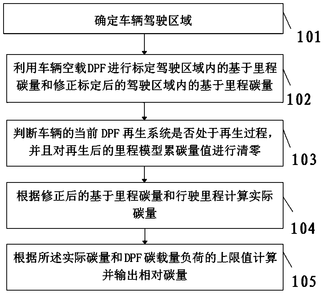
[0045] like figure 1 As shown, according to the embodiment of the present invention, the method for estimating the carbon accumulation of the diesel vehicle pa...


PUM


Abstract

The invention provides a carbon accumulation amount estimation method for a diesel vehicle particle trap. The carbon accumulation amount estimation method for the diesel vehicle particle trap comprises the steps that the vehicle driving area is determined; a vehicle-mounted no-load DPF is utilized for calibrating and correcting the mileage based carbon amount in the driving area; whether a currentDPF regeneration system of a vehicle is in the regeneration process or not is judged, and the regenerated mileage model carbon accumulation amount value is reset; the actual carbon amount is calculated on the basis of the mileage based carbon amount and the driving mileage; and the relative carbon amount is calculated and output according to the actual carbon amount and the upper limit value of the DPF carbon capacity load. According to the carbon accumulation amount estimation method for the diesel vehicle particle trap in the embodiment, the carbon accumulation amount of the particle trap can be accurately estimated, the estimation result reliability is high, the DPF is reasonably regenerated in time, and the problems about pollution and vehicles due to untimely DPF regeneration are solved.

Description

technical field [0001] The invention relates to the technical field of vehicle manufacturing, in particular to a method for estimating the carbon accumulation of a diesel vehicle particulate filter. Background technique [0002] With the rapid development of the automobile industry, the exhaust of diesel vehicles has become one of the main sources of air pollution. The annual consumption of domestic diesel has reached 125 million tons and continues to increase at a rate of 5%-6% per year. The exhaust emission standards of vehicles are constantly improving. my country's diesel vehicles are about to fully implement the fifth stage of emission regulations, which is what we usually call the National V emission standards, which put forward stricter requirements for particulate matter, so more effective exhaust gas treatment must be adopted measure. [0003] In terms of exhaust emissions, compared with gasoline vehicles, the biggest problem of diesel vehicles is particle pollutants...

Claims


Application Information

Patent Timeline
Patent Type & Authority Patents(China)
IPC IPC(8): F01N11/00F01N9/00
CPCY02T10/40
Inventor 赵志国张寅徐蒙
Owner BEIJING AUTOMOBILE RES GENERAL INST
Why Eureka
Try Eureka