Throttling air energy water heater

An air energy water heater and water tank technology, which is applied to fluid heaters, fluid circulation arrangements, lighting and heating equipment, etc. The effect of water utilization rate, reducing mixing speed, and improving energy saving effect

Pending Publication Date: 2018-01-19
广西昊薪来新能源有限公司
View PDF8 Cites 2 Cited by
  • Summary
  • Abstract
  • Description
  • Claims
  • Application Information

AI Technical Summary

Problems solved by technology

However, the existing air-energy water heaters only heat the cold water in the entire water tank to the required temperature, and for the situation that the water consumption is small and the whole tank of hot water cannot be used up, the existing air-energy water heaters have no better means to deal with it. In this case, the whole tank of water is still heated, resulting in waste of hot water and energy, and increasing the user's use cost
At the same time, the incoming water of the existing water heater directly enters the water tank at a relatively high speed through this water heater inlet pipe assembly, resulting in serious mixing of hot and cold water, and a large drop in the temperature of some hot water, resulting in the amount of hot water that can be directly used. reduce
Moreover, the existing water heaters do not have a magnetization device, which is prone to fouling after a long time, which affects the service life of the water heater

Method used


Image

  • Throttling air energy water heater
  • Throttling air energy water heater
  • Throttling air energy water heater

Examples


Embodiment Construction

[0032] The present invention will be further described in detail below in conjunction with the accompanying drawings, so that those skilled in the art can implement it with reference to the description.

[0033] It should be understood that terms such as "having", "comprising" and "including" as used herein do not entail the presence or addition of one or more other elements or combinations thereof.

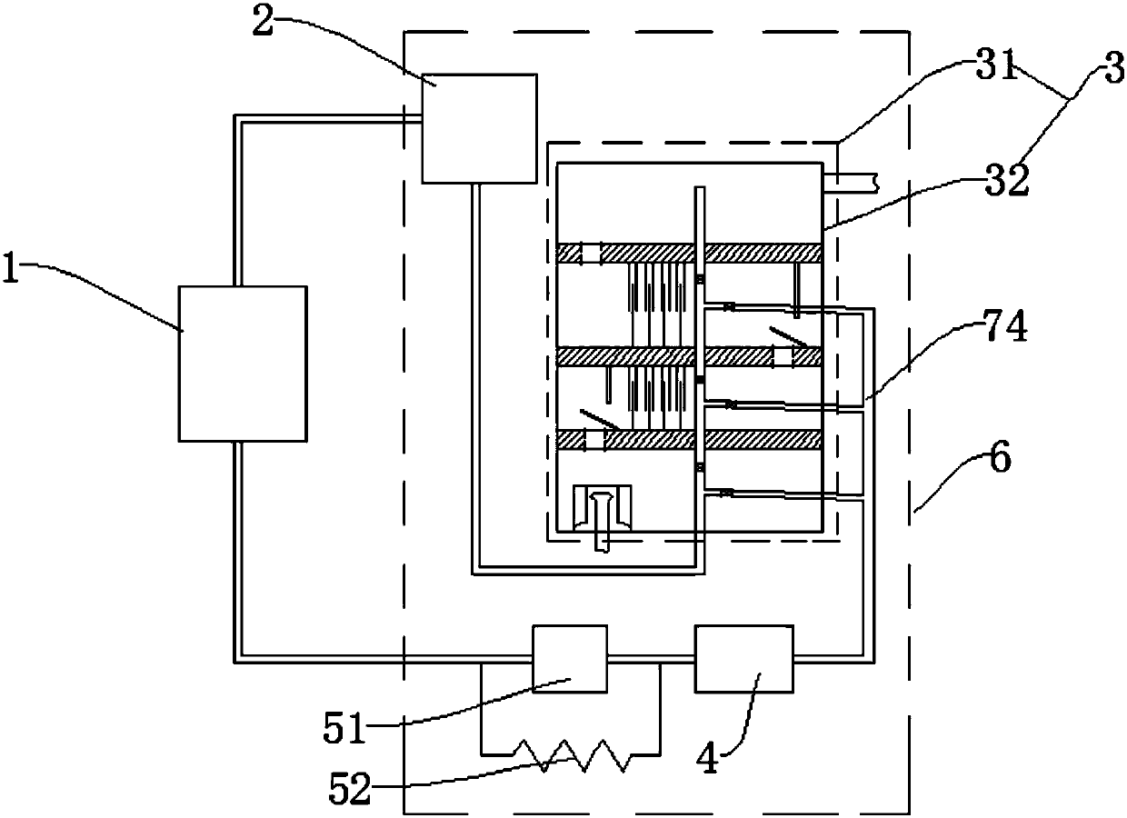
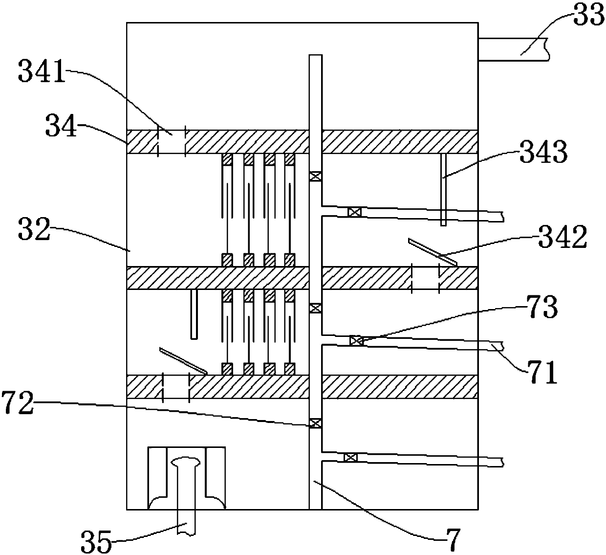
[0034] Such as Figure 1-8 As shown, a throttling air energy water heater includes an evaporator 1, a compressor 2, a condenser 3, a filter 4 and an electronic expansion valve 51 connected through a refrigerant pipeline circulation, a compressor 2, a condenser 3, and a filter 4 and electronic expansion valve 51 are installed in a cylinder 6, the condenser 3 includes a housing 31, also includes:

[0035] The water tank 32 is located in the housing 31. The upper end of the water tank 32 is provided with a hot water outlet pipe 33, and the lower end of the water tank 32 is provided...


PUM


Abstract

The invention discloses a throttling air energy water heater. The throttling air energy water heater includes an evaporator, a compressor, a condenser, a filter and an expansion valve which are connected with one another through a refrigerant pipeline in a circulation mode. The throttling air energy water heater also includes a water tank, multiple dummy plates, magnetizing components and a condensation pipe, wherein the upper end of the water tank is provided with a hot water outlet pipe and the lower end of the water tank is provided with a cold water inlet pipe and a refrigerant inlet; a spherical part is installed at the upper end of the cold water inlet pipe; a first sleeve is externally installed on the cold water inlet pipe in a sleeving mode; a second sleeve is externally installedon the first sleeve in a sleeving mode; the interior of the water tank is divided into multiple spaces by the dummy plates and each dummy plate is provided with an arc-shaped hole; the magnetizing components are installed between the dummy plates; the condensation pipe penetrates through the multiple dummy plates from bottom to top; each part, located in each space, of the condensation pipe communicates with a first branch pipe and the multiple first branch pipes communicate with second branch pipes located outside the water tank. According to the throttling air energy water heater, the flowspeed of cold water entering the water tank is reduced through guiding holes formed in the exteriors of the spherical part, the first sleeve and the second sleeve so that the mixing speed of originalhot water and the cold water in the water tank is reduced, and the use ratio of the hot water is increased.

Description

technical field [0001] The invention relates to the field of water heaters, more specifically the invention relates to a throttling air energy water heater. Background technique [0002] Air energy water heaters, also known as heat pump water heaters, or air source water heaters, are devices that use the working principle of heat pumps to absorb heat from the air to produce hot water. The air-energy water heater transfers the heat in the environment to the water by allowing the refrigerant to continuously complete the thermodynamic cycle of evaporation, compression, condensation, throttling, and re-evaporation. The power consumption of air-energy water heaters is usually only a quarter of that of electric water heaters, and it does not need to rely on sunlight for heating like solar water heaters. Since the work of air-energy water heaters is realized through heat exchange with refrigerants, electric heating elements are not required. In contact with water, there will be no...

Claims


Application Information

Patent Timeline
Patent Type & Authority Applications(China)
IPC IPC(8): F24H4/02F24H9/20F25B41/06F25B41/20F25B41/34F25B41/37
Inventor 刘兴文
Owner 广西昊薪来新能源有限公司
Why Eureka
Try Eureka