Geological radar protection device with abrasion-resistant function

A technology of geological radar and protection device, which is applied in radio wave measurement systems, instruments, etc., can solve the problems of wear and tear of geological radar antenna casing, collision, wear and collision of geological radar antenna, etc.

Pending Publication Date: 2018-01-19
四川嘉义新能有限公司
View PDF0 Cites 0 Cited by
  • Summary
  • Abstract
  • Description
  • Claims
  • Application Information

AI Technical Summary

Problems solved by technology

[0004] The technical problem to be solved by the present invention is that the geological radar antenna is prone to wear and collision during movement and use, and the purpose is to provide a geological radar protection device with anti-wear function to solve the problem that the geological radar antenna shell is subject to wear and collision

Method used


Image

  • Geological radar protection device with abrasion-resistant function
  • Geological radar protection device with abrasion-resistant function

Examples


Embodiment 1

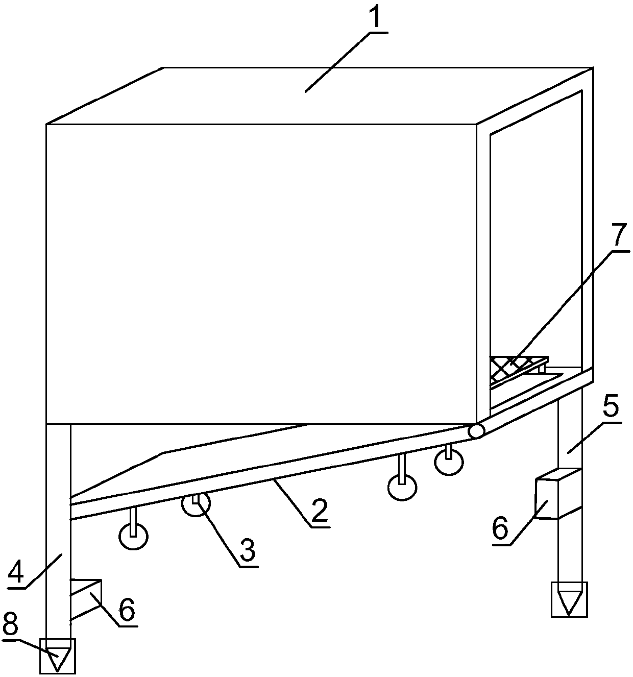
[0023] Such as figure 1 , figure 2 As shown, the geological radar protection device with anti-wear function of the present invention includes a cuboid casing 1 wrapped outside the antenna casing, one side and bottom surface of the casing 1 are completely open, and one side outer wall of the bottom surface of the casing 1 The bottom plate 2 is hinged to block the bottom opening, and the bottom plate 2 reciprocates between the side opening and the bottom opening of the housing 1 around the hinged end, and at least three rollers in contact with the ground are arranged on one side of the bottom plate 2 3. At least one pair of telescopic rod groups are connected under the bottom of the housing 1, the telescopic rod groups include a first telescopic rod 4 and a second telescopic rod 5, the first telescopic rod 4 and the second telescopic rod 5 are respectively located in the housing 1. The bottom surface is at two corners on the same diagonal line. Both the first telescopic rod 4 ...

Embodiment 2

[0026] Based on Embodiment 1, the inside of the housing 1 is provided with a slide plate 7 for placing the antenna housing, and a slide bar is provided below the slide plate 7 to interact with the opening wall at the bottom of the housing 1, and the opening wall at the bottom of the housing 1 is provided with The slide rail matched with the slide bar, the sliding direction of the slide plate 7 is the same as the rolling direction of the roller 3 . The slide plate 7 adopts a hollowed-out mesh aluminum plate. The slide plate is used to place the radar antenna to avoid the large loss caused by the friction between the radar antenna shell and the shell when the radar antenna enters the shell from the side opening, which effectively reduces the wear of the radar shell; the slide bar is slidably connected with the slide rail , move fast and save time.

Embodiment 3

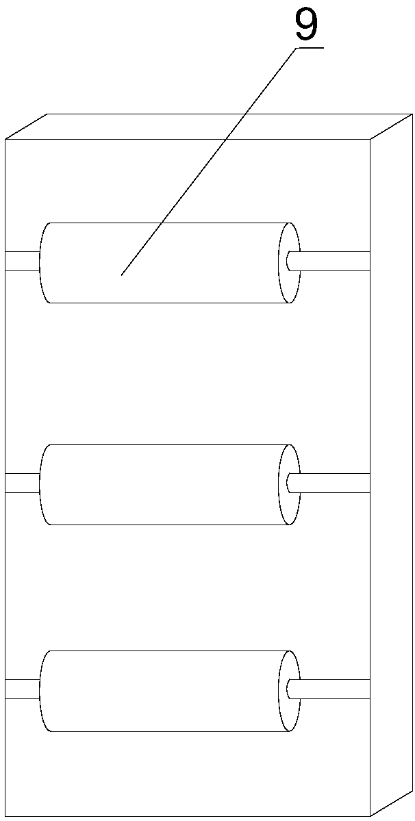
[0028] Based on the above-mentioned embodiment, a plurality of roller shafts 9 arranged in parallel are installed on one side of the bottom plate 2 , all the roller shafts 9 are located on the same side as the rollers 3 , and the rolling directions of all the roller shafts 9 are the same as the rolling directions of the rollers 3 . The rolling of the roller shaft can also drive the housing to move. When the roller is damaged, the roller shaft is used, and the roller shaft plays a backup role.


PUM


Abstract

The invention discloses a geological radar protection device with an abrasion-resistant function. The geological radar protection device comprises a rectangular shell, the rectangular shell wraps theoutside of an antenna shell, openings are formed in one side surface and the bottom surface of the rectangular shell, a bottom plate is hinged on the outer wall of one side of the bottom surface of the shell and used for plugging the opening in the bottom surface, the bottom plate reciprocates between the openings of the side surface and the bottom surface of the shell around a hinge end, at leastthree rollers are arranged on one side surface of the bottom plate and contact with the ground, at least one pair of telescopic rod groups are connected on the lower portion of the bottom of the shell and include first telescopic rods and second telescopic rods, each first telescopic rod and the corresponding second telescopic rod are positioned at two corners on the same diagonal line on the bottom surface of the shell, horizontal plates are arranged on the first telescopic rods and the second telescopic rods and used for locking the bottom plate and contact with the bottom plate, and the horizontal plates are positioned below the bottom plate. The protection device solves the problems of abrasion and collision of the geological radar antenna shell by the aid of the shell with the rollers.

Description

technical field [0001] The invention relates to a radar protection cover, in particular to a geological radar protection device with anti-wear function. Background technique [0002] Geological radar is the abbreviation of geological radar for detecting underground objects. Its basic principle is: the transmitter transmits pulsed electromagnetic wave signals with a center frequency of 12.5M to 1200M and a pulse width of 0.1ns through the transmitting antenna. When this signal meets the detection target in the rock formation, a reflected signal will be generated. The direct signal and reflected signal are input to the receiver through the receiving antenna, and displayed by the oscilloscope after amplification. According to whether the oscilloscope has a reflection signal, it can be judged whether there is a target under test; according to the arrival delay time of the reflection signal and the average reflection wave velocity of the target object, the distance of the detect...

Claims


Application Information

Patent Timeline
Patent Type & Authority Applications(China)
IPC IPC(8): G01S7/03
Inventor 杨浩
Owner 四川嘉义新能有限公司
Why Eureka
Try Eureka