Method for calculating end contact collision force of spatial robot

A space robot and computing method technology, applied in computing, instruments, special data processing applications, etc., can solve problems such as mechanical arm or target damage, complex dynamic behavior, and high test complexity, achieving good compactness and simple calculation. , the effect of improving efficiency

Active Publication Date: 2018-01-19
BEIJING INST OF CONTROL ENG
View PDF2 Cites 12 Cited by
  • Summary
  • Abstract
  • Description
  • Claims
  • Application Information

AI Technical Summary

Problems solved by technology

[0002] During the capture process of the target star-rocket docking ring by the clamping tool at the end of the space robot, the clamping tool and the star-rocket docking ring will inevitably collide and impact, and the two bodies will show sliding friction, rigid collision and separation during the collision process. A variety of motion forms make the dynamic behavior in the capture process more complicated, and also affect the success or failure of the capture task
On the other hand, a direct collision will cause damage to the robotic arm or the target. For time-limited high-quality operation control, the information of the contact force must be introduced into the closed control loop, so that the contact force can be controlled within the allowable range to complete compliant capture.
At present, ground tests are used to obtain the collision information of the two. First, the complexity of the test is high, and second, the repeatability of the test is poor.

Method used


Image

  • Method for calculating end contact collision force of spatial robot
  • Method for calculating end contact collision force of spatial robot
  • Method for calculating end contact collision force of spatial robot

Examples


Embodiment Construction

[0040] Below in conjunction with accompanying drawing, the present invention is described in further detail:

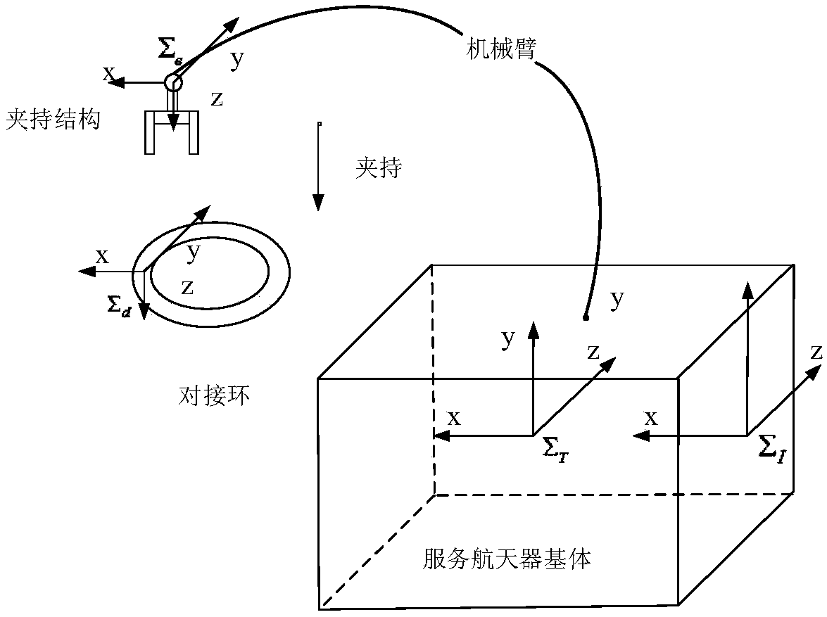
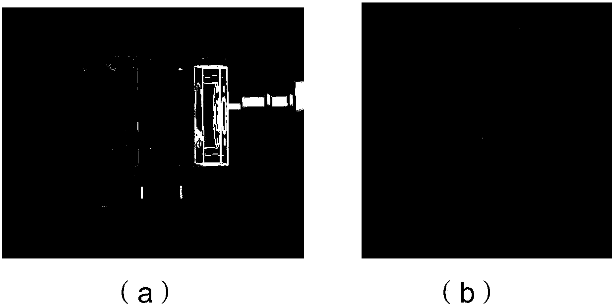
[0041] The clamping tool is connected to the base body of the service spacecraft through a six-degree-of-freedom space manipulator, and the positioning and attitude determination are realized through the in-orbit movement of the space manipulator to ensure that it can contact the docking ring of the target star and clamp the docking ring , the relative pose of the clamping tool and the docking ring when clamping and capturing is as follows figure 1 as shown, figure 2 (a) and figure 2 (b) shows the CAD model of the holding tool and docking ring. In this embodiment, the capturing device is selected as a clamping tool, and the captured device is selected as a docking ring. For the process of clamping the docking ring, set the material properties, geometric parameters and control parameters for simulation. The centroid of each rigid body is at its geometric center, ...


PUM


Abstract

The invention discloses a method for calculating end contact collision force of a spatial robot. The method comprises the following steps of simplifying mechanical design three-dimensional CAD modelsof a capture apparatus and a captured apparatus; performing feature geometric element extraction on built triangular plate element models of the capture apparatus and the captured apparatus; accordingto geometric feature models of the capture apparatus and the captured apparatus, obtaining collision point positions and embedding depth quantities of the capture apparatus and the captured apparatus; building collision models of the capture apparatus and the captured apparatus; through a collision embedding quantity and a collision embedding speed, obtaining collision force; through a tangentialspeed of the collision embedding speed, the collision force and a frictional coefficient, obtaining contact frictional force; and in combination with the collision force and the contact frictional force, obtaining a collision force model. For an irregular target geometric configuration, an efficient collision detection method for simplifying geometric features is provided, and support is providedfor simulative verification work of manipulator joint bearing and capture control schemes.

Description

technical field [0001] The invention belongs to the field of on-orbit repair and maintenance of space robots, and relates to a calculation method for contact collision force at the end of a space robot, which is suitable for capturing operations on space non-cooperative targets such as space faulty satellites and large debris. Background technique [0002] During the capture process of the target star-rocket docking ring by the clamping tool at the end of the space robot, the clamping tool and the star-rocket docking ring will inevitably collide and impact, and the two bodies will show sliding friction, rigid collision and separation during the collision process. A variety of motion forms make the dynamic behavior in the capture process more complicated, and also affect the success or failure of the capture task. On the other hand, direct collisions will cause damage to the robotic arm or the target. For time-limited high-quality operation control, the contact force informat...

Claims


Application Information

Patent Timeline
Patent Type & Authority Applications(China)
IPC IPC(8): G06F17/50
Inventor 张海博何英姿魏春岭魏承王勇徐拴锋
Owner BEIJING INST OF CONTROL ENG
Why Eureka
Try Eureka