
High and low voltage electric porcelain arrester

A lightning arrester, high-voltage and low-voltage technology, applied in the field of lightning arresters, can solve the problems of high failure rate of catenary lightning strikes, fatal injuries to trains and personnel, and inability to realize large-area lightning protection, etc., to achieve good lightning protection effect, simple installation hoop structure, and convenient assembly Effect

Inactive Publication Date: 2018-01-19
WUHU KAIXIN ARRESTER
View PDF5 Cites 3 Cited by
  • Summary
  • Abstract
  • Description
  • Claims
  • Application Information

AI Technical Summary

Problems solved by technology

[0003] (1) In terms of the insulation configuration of the current lightning arrester device, the insulation level of the catenary is only equivalent to that of the 35kV power distribution overhead line of the power system, and the lightning resistance level is low, and lightning protection measures are only set on some key nodes, which may easily lead to high-speed railway contact. The lightning strike failure rate of the network is relatively high;
[0004] (2) The existing lightning arrester installation device has a large volume, and the installation workers have to set lightning protection measures on the pipe joints, which cannot realize large-scale lightning protection;
[0005] (3) The existing lightning arrester device does not have a pressure release device. When the lightning arrester is used for a long time for the catenary, when the resistor sheet causes a short circuit fault due to deterioration, high current breakdown or thermal collapse, if some components (such as the resistor sheet, metal pad, Electrodes, etc.) are damaged and fall off, which is likely to cause fatal injuries to trains and personnel passing by at high speed

Method used


Image

  • High and low voltage electric porcelain arrester
  • High and low voltage electric porcelain arrester
  • High and low voltage electric porcelain arrester

Examples


Embodiment

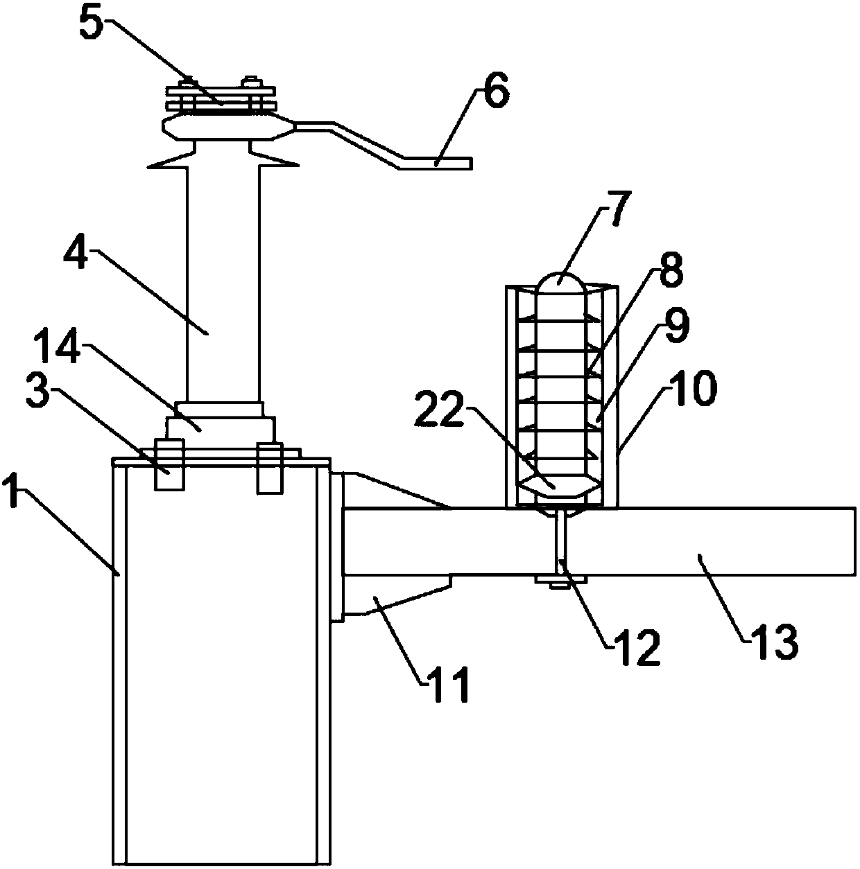
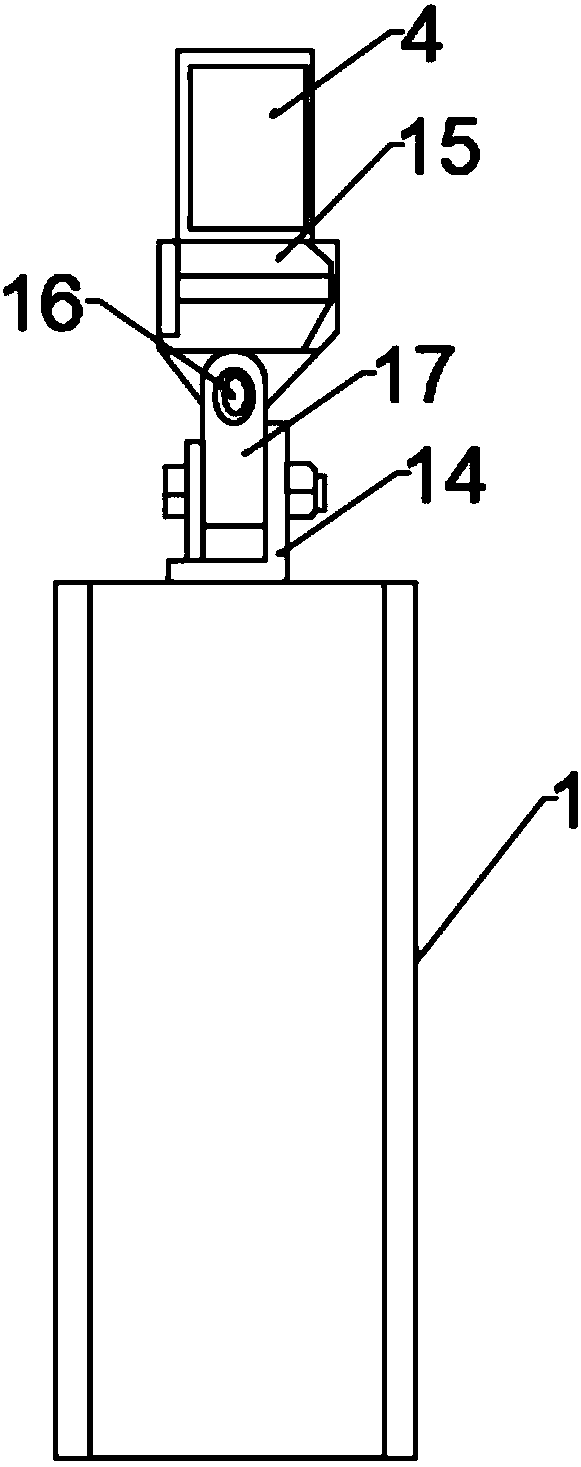
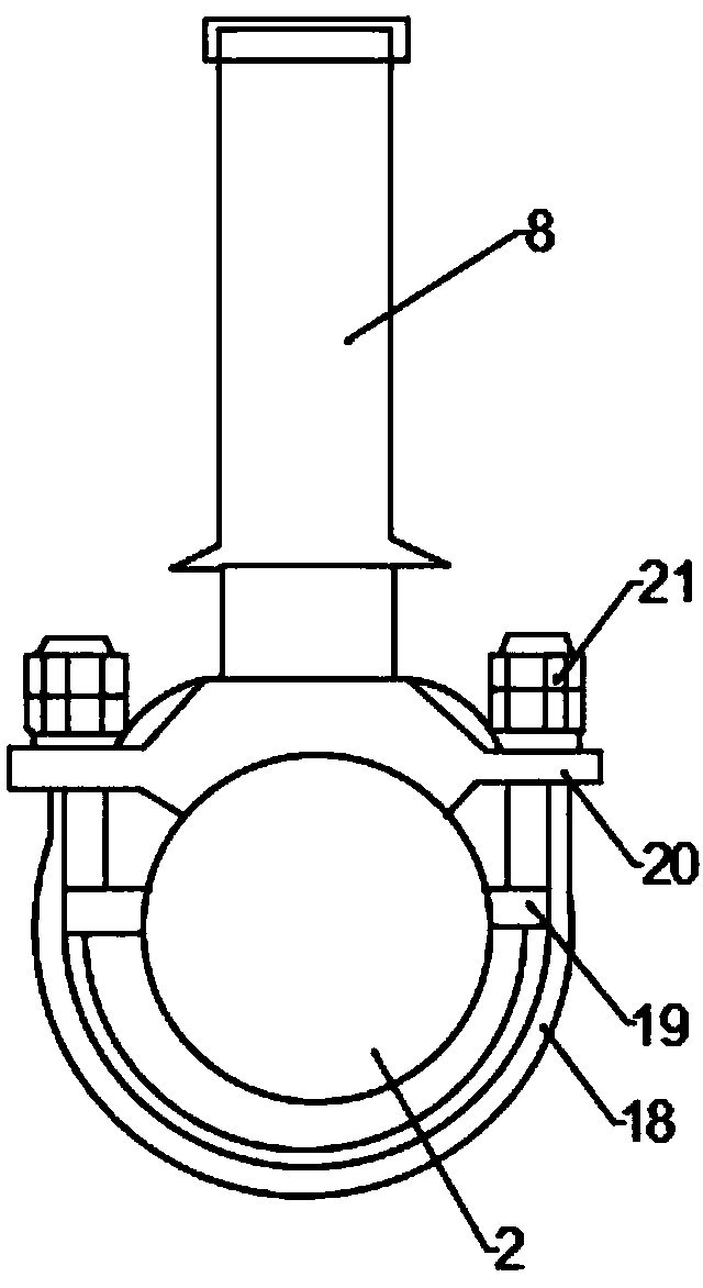
[0025] Such as figure 1 with image 3 As shown, the present invention provides a high and low voltage electric porcelain lightning arrester, comprising a lightning arrester pillar 1 and a pillar insulator 4, the upper surface of the lightning arrester pillar 1 is fixedly installed with a pillar insulator 4 through an adjusting bolt 3, and the upper end of the pillar insulator 4 is set There is a JQ line interface 5, the right end of the JQ line interface 5 is provided with an electrode rod 6, and the right side of the arrester pillar 1 is also connected to the cantilever beam 13 through a fixed bracket 11, and the fixed bracket 11 is connected to the arrester pillar 1 Fixed connection, the upper surface of the cantilever beam 13 is provided with a lightning arrester body 8, the lower end of the lightning arrester body 8 is embedded on the inner wall of the cantilever beam 13 through the lightning arrester installation device 12, and the upper end of the lightning arrester body...


PUM


Abstract

The invention discloses a high and low voltage electric porcelain arrester, which comprises an arrester post and a post insulator, wherein the upper surface of the arrester post is fixedly provided with the post insulator through adjusting bolts; a JQ line interface is arranged in the upper end of the post insulator; an electrode bar is arranged at the right end of the JQ line interface; the rightside surface of the arrester post is also connected with a cantilever beam through a fixing bracket; an arrester body is arranged on the upper surface of the cantilever beam; the lower end of the arrester body is inlaid into the inner wall of the cantilever beam through an arrester mounting device; and a hemispherical electrode is also fixedly arranged at the upper end of the arrester body. A certain gap exists between designed electrodes according to the operation characteristics and operation safety requirements of a contact network, so that the bearing capacity of the arrester body is reduced, the service life of the arrester is prolonged, the whole arrester is arranged more stably by using a mounting hoop, and the high and low voltage electric porcelain arrester is simple in mountingstructure and high in practicability.

Description

technical field [0001] The invention relates to the technical field of lightning arresters, in particular to a high and low voltage electric porcelain lightning arrester. Background technique [0002] The viaduct sections of China's high-speed railway lines have a large proportion, and they are relatively concentrated in areas with strong lightning activities. There are many lightning strike faults in the traction power supply catenary, and measures must be taken to solve them: [0003] (1) In terms of the insulation configuration of the current lightning arrester device, the insulation level of the catenary is only equivalent to that of the 35kV power distribution overhead line of the power system, and the lightning resistance level is low, and lightning protection measures are only set on some key nodes, which may easily lead to high-speed railway contact. The lightning strike failure rate of the network is relatively high; [0004] (2) The existing lightning arrester ins...

Claims


Application Information

Patent Timeline
Patent Type & Authority Applications(China)
IPC IPC(8): H01C7/12H01T1/16H01B17/46
Inventor 陈波
Owner WUHU KAIXIN ARRESTER
Learn More