
Lightning protection circuit of direct-current system

A technology of lightning protection circuit and DC system, applied in emergency protection circuit device, emergency protection circuit device for limiting overcurrent/overvoltage, protection against overcurrent, etc., can solve the problem of high cost of grounding grid construction , inability to short-circuit DC equipment, uncontrollable lightning protection effects, etc., to reduce construction and maintenance costs, optimize lightning protection effects, and shorten construction periods

Active Publication Date: 2013-09-11
SHENZHEN YZ TECH
View PDF7 Cites 7 Cited by
  • Summary
  • Abstract
  • Description
  • Claims
  • Application Information

AI Technical Summary

Problems solved by technology

[0006] The purpose of the embodiments of the present invention is to provide a lightning protection circuit for a DC system, which aims to solve the problem that in the current lightning protection mode of a DC system, there is only one level of surge protector, and the surge protector cannot fully protect the DC equipment. If it is short-circuited, part of the lightning strike current flows through the protected load equipment, and the lightning protection effect is uncontrollable. At the same time, due to the limitation of the resistance value of the grounding grid, the construction cost of the grounding grid is high.

Method used


Image

  • Lightning protection circuit of direct-current system
  • Lightning protection circuit of direct-current system
  • Lightning protection circuit of direct-current system

Examples


Embodiment 1

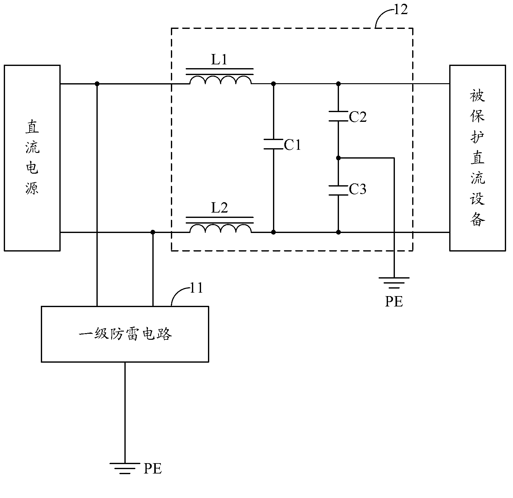
[0019] Embodiment 1 of the present invention proposes a lightning protection circuit for a DC system, such as figure 1 As shown, for ease of description, only the part related to Embodiment 1 of the present invention is shown.

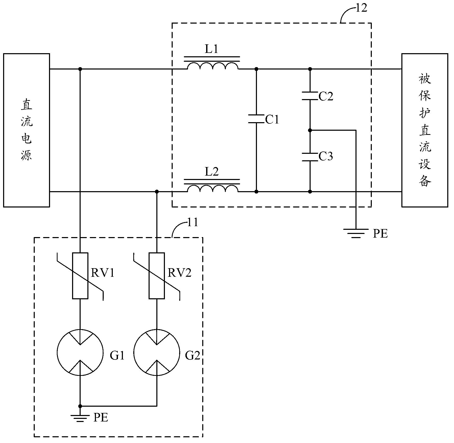
[0020] In detail, the lightning protection circuit of the DC system provided by the embodiment of the present invention includes: a first-level lightning protection circuit 11 connected in parallel between the two output terminals of the DC power supply and the lightning protection grounding PE line, used to provide lightning current The discharge path: the lightning current suppression circuit 12 arranged between the primary lightning protection circuit 11 and the protected DC equipment, and connected in series on the power supply path from the DC power supply to the protected DC equipment.

[0021] Further, the lightning current suppression circuit 12 includes: a magnetic core inductor L1, a magnetic core inductor L2, a capacitor C1, a capacitor C2, ...

Embodiment 2

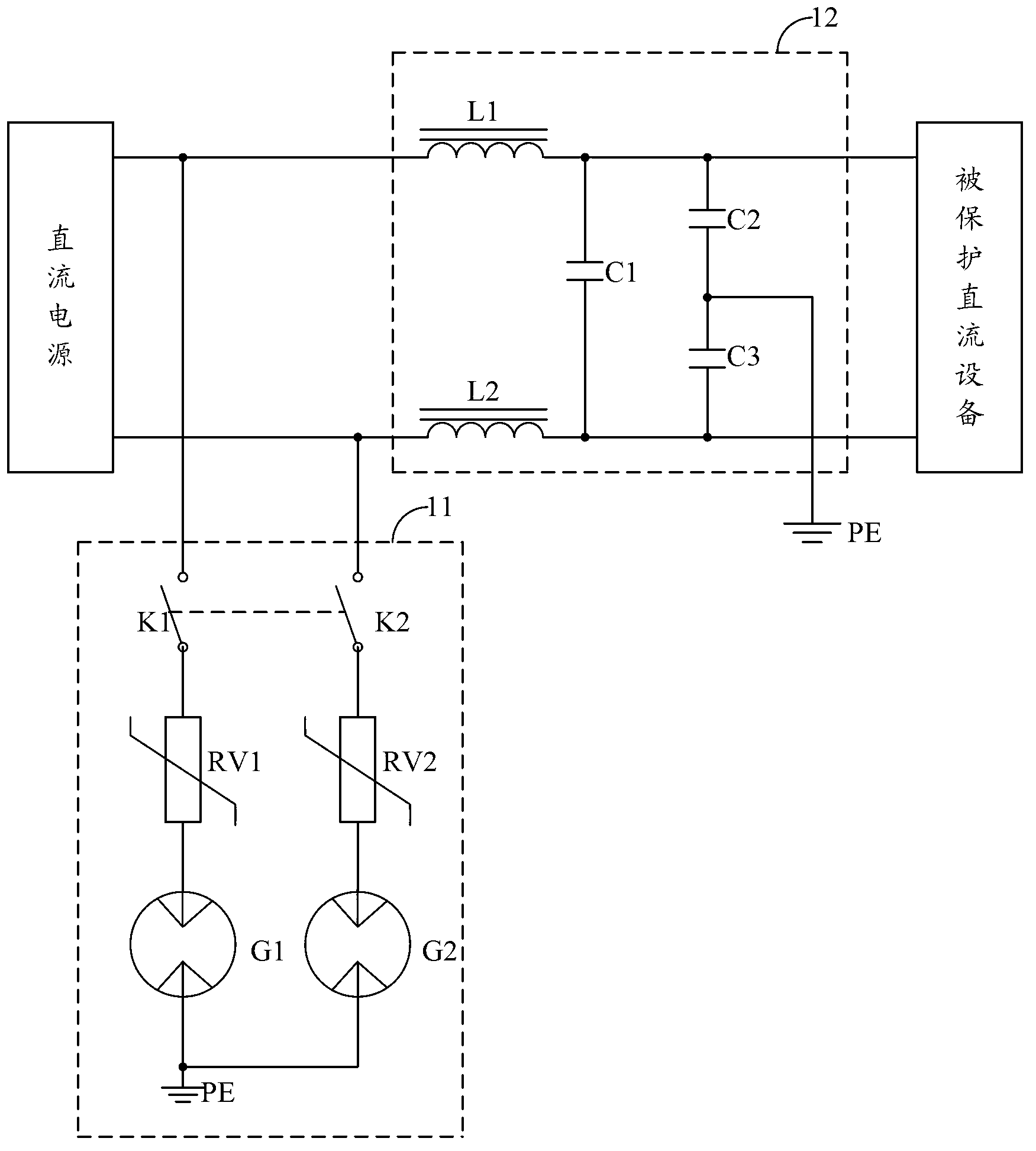
[0028] Embodiment 2 of the present invention proposes a lightning protection circuit for a DC system, such as Figure 5 As shown, for ease of description, only the part related to Embodiment 2 of the present invention is shown.

[0029] Since after passing through the first-level lightning protection circuit 11 and the lightning current suppression circuit 12, a part of the energy close to direct current in the lightning current spectrum still remains, in order to further filter out this part of the remaining lightning current energy, different from the first embodiment, in the second embodiment Among them, the lightning protection circuit of the DC system also includes: a secondary lightning protection circuit 12 connected in parallel between the positive and negative input terminals of the protected DC equipment and the lightning protection grounding PE line of the protective conductor, used to provide A discharge path for the residual lightning current of the current suppress...


PUM


Abstract

The invention belongs to the design field of lightning protection circuits, and provides a lightning protection circuit of a direct-current system. The circuit comprises a primary lightning protection circuit which is in parallel connection with to-be-protected direct-current equipment in the direct-current system. A lightning current suppression circuit is in parallel connection between the primary lightning protection circuit and the to-be-protected direct-current equipment. When lightning currents are introduced through a power wire, and a part of lightning currents pass a primary lightning protection discharging place. Then, transient high impedance is formed as for remained lightning current waveforms by the lightning current suppression circuit, so that the primary lightning protection circuit can be connected quickly to discharge more lightning current energy, the lightning currents are prevented from spreading along the power wire and lightning protection effect is optimized. Meanwhile, discharging distribution of the lightning currents no longer only depends on resistance of a grounding grid and characteristic impedance of the to-be-protected equipment, so that resistance requirements on the grounding grid can be relaxed, construction and maintenance costs of the grounding grid are remarkably reduced and construction period of the grounding grid is shortened.

Description

technical field [0001] The invention belongs to the field of lightning protection circuit design, in particular to a lightning protection circuit applied in a direct current system. Background technique [0002] In the prior art, the lightning protection method of the DC system is to provide a grounding network with a small grounding resistance. If the DC equipment and AC equipment of the DC system are together, it is only necessary to connect the grounding point of the DC equipment with the grounding grid; if the DC equipment and AC equipment of the DC system are not The base stations of the AC power supply are far apart, and the long overhead lines are likely to be invaded by direct lightning or induced lightning again. In this case, a special grounding network must be built to cooperate with the surge protector to discharge the lightning current. [0003] In the lightning protection method of the above-mentioned DC system, the smaller the resistance value of the groundin...

Claims


Application Information

Patent Timeline
Patent Type & Authority Applications(China)
IPC IPC(8): H02H9/02H02H9/06H02H3/08
Inventor 刘先绿张庭炎汤文
Owner SHENZHEN YZ TECH
Learn More