An elbow welding positioning and locking device

A welding positioning and locking device technology, applied in welding equipment, auxiliary equipment, auxiliary welding equipment, etc., can solve problems such as poor fixation, scrapped pipe fittings, cumbersome alignment steps of pipe fittings, etc.

Active Publication Date: 2018-07-06
GUANGDONG JUNCHI TECH HLDG
View PDF5 Cites 3 Cited by
  • Summary
  • Abstract
  • Description
  • Claims
  • Application Information

AI Technical Summary

Problems solved by technology

This welding method mainly has the following defects: 1) because the first pipe tube 81, the straight pipe 82 with branch pipe 85, the bent pipe 83 and the second tube tube 84 are all circular pipe fittings, which are easy to slide and difficult to fix. Moreover, there are many welding positions and the size of the pipe fittings is not large, which easily leads to missing welding or poor welding; 2) the welding angle of the branch pipe 85 and the elbow pipe 83 is difficult to manually grasp, and a slight vibration will cause welding errors and cause the pipe fittings to be scrapped; 3) The depth of the straight pipe 82 inserted into the first tube 81 and the depth of the bent tube 83 inserted into the second tube 84 are not easy to control, which may easily lead to differences in the dimensions of the produced multi-channel tubing, and cannot guarantee the same batch Product quality; 4) The alignment steps of pipe fittings are cumbersome and the welding efficiency is low, which has become more and more difficult to meet the requirements of modern production of car light brackets
However, in this application, it can only be used for ordinary pipe fittings, and it is impossible to achieve accurate alignment of the welding angle between the straight pipe with the branch pipe and the elbow pipe, and its locking requires additional power such as a cylinder, the locking speed is slow, and the power consumption is large.

Method used


Image

  • An elbow welding positioning and locking device
  • An elbow welding positioning and locking device
  • An elbow welding positioning and locking device

Examples


Embodiment

[0028] Embodiment: An elbow welding positioning and locking device.

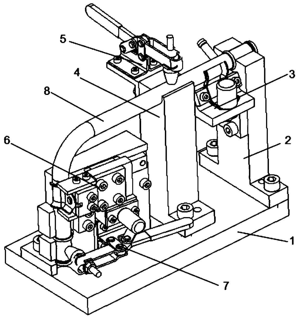
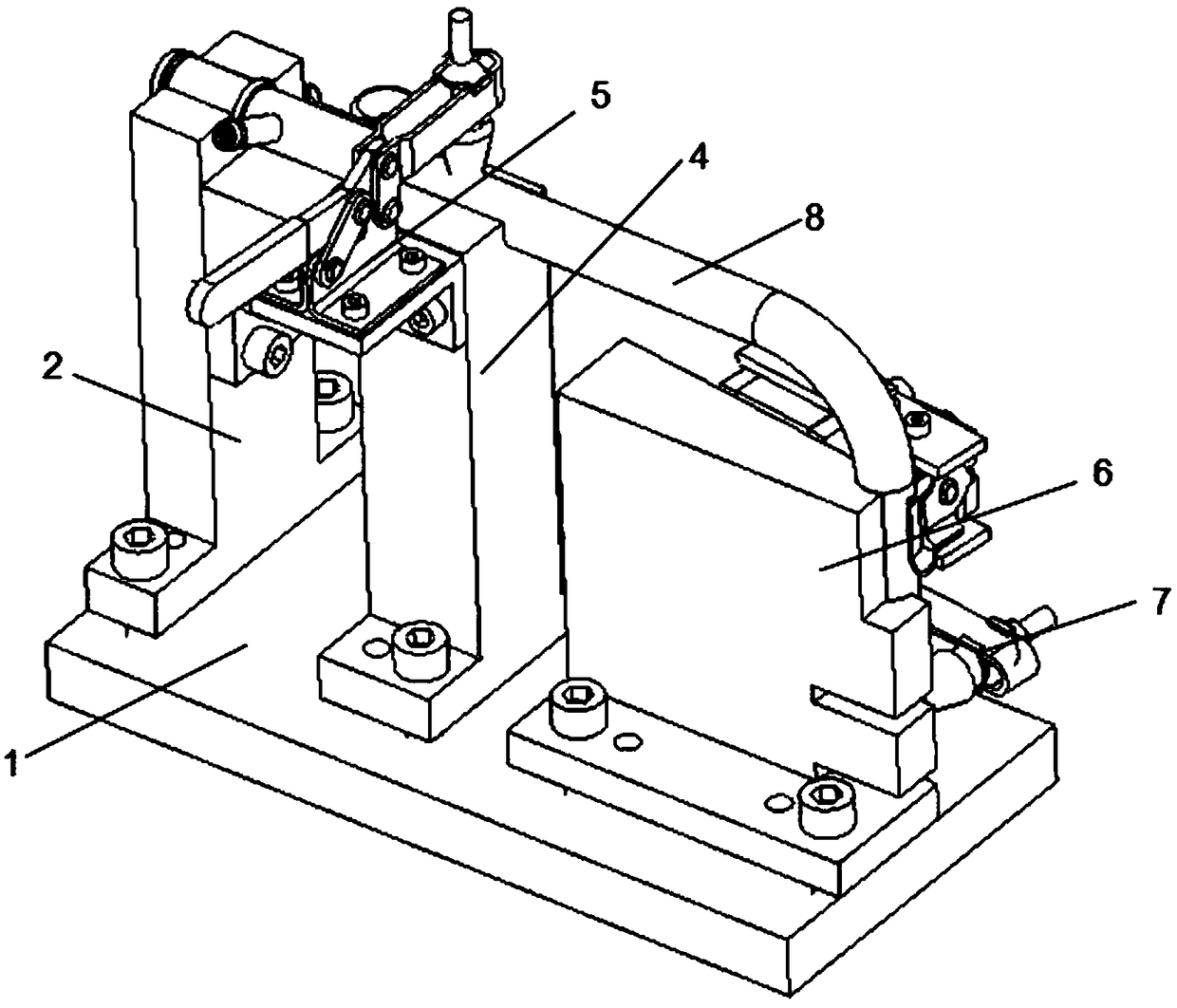
[0029] refer to Figure 1 to Figure 9 As shown, a elbow welding positioning and locking device includes:

[0030] Base 1, the base 1 is a metal plate, used to provide installation space for components such as the first support base 2, the second support base 4 and the elbow positioning mechanism 6;

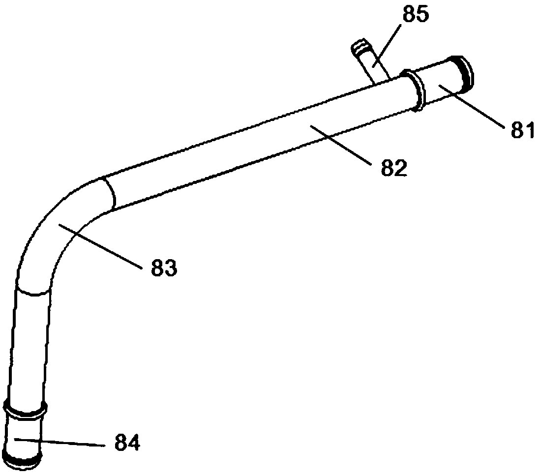
[0031] The first support seat 2, the second support seat 4 and the elbow positioning mechanism 6 are installed in parallel on the base 1 in turn from right to left. The top of the first support seat 2 is provided with a first positioning groove 21, and the second support seat The top of the seat 4 is provided with a second positioning groove 41, and the centers of the first positioning groove 21 and the second positioning groove 41 are located on the same horizontal straight line, and the length of the first positioning groove 21 is the same as that of the first tube. The tubes 81 have the same length, so that...


PUM


Abstract

The invention provides an elbow welding positioning and locking device, comprising: a base; a first support base, a second support base and an elbow positioning mechanism installed in parallel on the base from right to left; and the branch pipe positioning mechanism between the second support base; the first locking fixture installed on the second support base; the elbow positioning mechanism is installed on the left side of the second support base; fixed on the side wall of the elbow positioning mechanism and located Position the second locking clamp below the locking block. The elbow welding positioning and locking device can realize the rapid positioning and docking of pipe fittings of different shapes through the preset first support seat, second support seat, first locking fixture, elbow positioning mechanism, and second locking fixture, and ensure Butt joint quality, the branch pipe positioning mechanism can ensure that the welding angle between the branch pipe and the first tube and the second tube meets the requirements, and the straight pipe and the second tube can be realized through the first locking fixture and the second locking fixture quick lock.

Description

technical field [0001] The invention relates to the technical field of auto parts processing, in particular to an elbow welding positioning and locking device. Background technique [0002] In the car structure, many parts belong to the tube and bracket. There are many types and shapes, and most of them require the use of tack welding technology. The multi-channel oil pipe is a key part of the automobile engine system, and its shape is as figure 1 As shown, the multi-channel oil pipe is generally welded by a first tube 81, a straight tube 82 with a branch 85, an elbow 83 and a second tube 84, wherein the first tube 81 and the second tube 84 are used for Butt the other parts of the engine, the branch pipe 85 on the straight pipe 82 is used for the butt joint of the branch oil circuit, so the welding angle of the branch pipe 86 on the straight pipe 82 and the first tube 81 and the second tube 85 must be accurate, once the angle appears If the above error is not correct, the...

Claims


Application Information

Patent Timeline
Patent Type & Authority Patents(China)
IPC IPC(8): B23K37/04
Inventor 余福光陈丁华黄富华
Owner GUANGDONG JUNCHI TECH HLDG
Why Eureka
Try Eureka