
Robot automatic glaze spraying system

A robot and glaze spray technology, applied in ceramic molding machines, manufacturing tools, etc., can solve problems such as increased production costs, lack of processing equipment, waste of glaze, etc.

Active Publication Date: 2018-01-23
FOSHAN PRATIC CNC SCI & TECH
View PDF7 Cites 4 Cited by
  • Summary
  • Abstract
  • Description
  • Claims
  • Application Information

AI Technical Summary

Problems solved by technology

However, in the existing robotic glazing system, the integrated fixed design of a single conveying line is adopted, and the production adaptability is low. It is not possible to increase or decrease the glazing station according to the change of production demand, and the production cost control is not flexible.
Moreover, the existing robotic glaze spraying system lacks processing equipment for the green body before and after spraying the glaze, and the green body with quality problems cannot be found in time before the glaze is sprayed, so that it can enter the spraying process, which not only wastes the glaze, but also improves the follow-up repair process. The blank body is difficult; after the glaze is sprayed, the blank body is not detected in time, and the unqualified blank body is easy to enter the next production process, so that an additional glaze repair conveyor line needs to be added to the overall production system, which greatly increases the production cost.

Method used


Image

  • Robot automatic glaze spraying system
  • Robot automatic glaze spraying system
  • Robot automatic glaze spraying system

Examples


Embodiment Construction

[0048] The technical solutions of the present invention will be further described below in conjunction with the accompanying drawings and through specific implementation methods.

[0049] The robot automatic glaze spraying system of present embodiment, as figure 1 As shown, it includes a pre-processing unit, a glaze spraying unit and a post-processing unit in sequence from upstream to downstream, and is characterized in that:

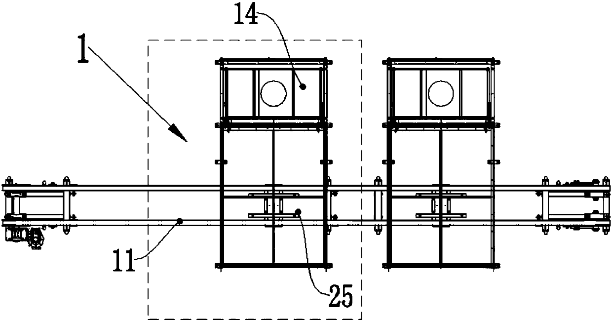
[0050] The pre-processing unit includes several pre-processing modules 1, such as figure 2 As shown, the pre-processing module 1 includes a trimming and dedusting station;

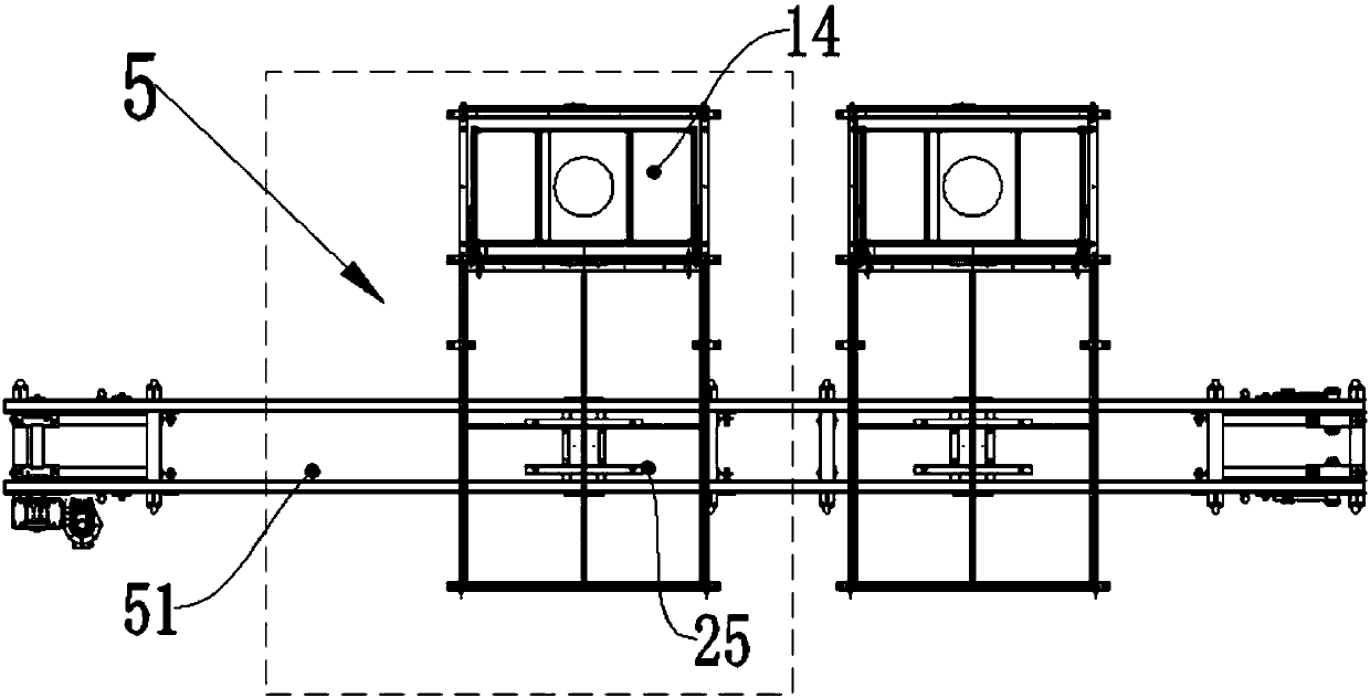
[0051] The post-processing unit includes several post-processing modules 5, such as image 3 As shown, the post-processing module 5 includes a detection and cleaning station;

[0052] Described spraying glaze unit comprises several spraying glaze modules 2, as Figure 4 As shown, the glaze spraying module 2 includes a glaze spraying conveyor line 21, a glaze spraying robot 22, ...


PUM


Abstract

The invention discloses a robot automatic glaze spraying system. The robot automatic glaze spraying system comprises a pretreatment unit, a glaze spraying unit and a posttreatment unit from upstream to downstream in sequence. The pretreatment unit comprises a plurality of pretreatment modules. Each pretreatment module comprises a blank trimming and dust collection position. The posttreatment unitcomprises a plurality of posttreatment modules. Each posttreatment module comprises a detecting and cleaning position. The glaze spraying unit comprises a plurality of glaze spraying modules. Each glaze spraying module comprises a glaze spraying conveying line, a glaze spraying robot and an air extraction and dust collection room. Each unit of the robot automatic glaze spraying system is a detachable module combination. The number of the pretreatment modules, the number of the glaze spraying modules and the number of the posttreatment modules can be set freely according to the production requirements. The production adaptability is greatly improved. The modules can be combined freely according to the production requirements. The design and development cycle of a glaze spraying production line is shortened. The number of the modules can be increased and reduced at will in the production process. The production cost is controlled flexibly.

Description

technical field [0001] The invention relates to the field of glaze spraying equipment, in particular to a robot automatic glaze spraying system. Background technique [0002] In the process of glaze spraying of traditional daily-use ceramic products, loading and unloading and spraying glaze are all done manually, which has low efficiency, high labor intensity, harsh production environment, and poor consistency of product spraying. With the advancement of science and technology, automatic glaze spraying robots have been applied in the production of daily-use ceramics, which greatly improve the efficiency and quality of glaze spraying. However, the existing robotic glazing system adopts an integrated fixed design with a single conveying line, which has low production adaptability, cannot increase or decrease the glazing stations according to changes in production requirements, and the production cost control is not flexible. Moreover, the existing robotic glaze spraying syste...

Claims


Application Information

Patent Timeline
IPC IPC(8): B28B11/04
Inventor 黄建行李爱军陈铭章李海波
Owner FOSHAN PRATIC CNC SCI & TECH
Learn More